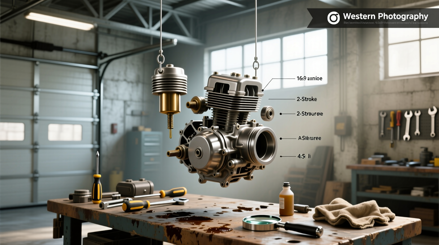
If you're searching for a 2 stroke carburetor diagram, you're likely trying to understand how fuel and air mix in small engines like those found in dirt bikes, chainsaws, or scooters. This guide delivers a clear breakdown of diaphragm-type 2-stroke carburetors—how they work, what each component does, and how to interpret a typical schematic. You’ll also learn about fuel delivery mechanics, common tuning issues, and how to identify problems using visual and functional clues from real-world diagrams and system behavior ⚙️.
What Is a 2 Stroke Carburetor and Why the Diagram Matters
A 2 stroke carburetor is a mechanical device responsible for mixing air and fuel in the correct ratio before delivering it to the engine’s combustion chamber. Unlike 4-stroke engines, which rely on atmospheric pressure and piston movement for intake, 2-stroke engines use crankcase pressure pulses to assist in fuel induction—making their carburetion systems uniquely designed 🔧.
Understanding a 2 stroke carburetor diagram is essential for anyone maintaining or repairing small displacement engines. These diagrams illustrate internal passages, fuel metering components, and airflow channels that aren’t visible externally. They help diagnose issues like flooding, lean running, or poor idle by showing where blockages or malfunctions might occur.
Most modern 2-stroke carburetors are of the diaphragm type (e.g., Walbro, Zama, or Tillotson), which differ significantly from float-style carbs used in many 4-strokes. The absence of a float bowl means fuel delivery depends on pulse pressure from the engine’s crankcase—a key concept any diagram must clarify.
Key Components in a Typical 2 Stroke Carburetor Diagram
When analyzing a 2 stroke carburetor parts diagram, several core elements appear consistently across brands and models. Here's a breakdown of what you’ll see and why each part matters:
- Throttle Valve (Butterfly): Controls airflow into the engine. Positioned between the air filter and venturi, this plate opens under throttle input to allow more air—and thus more fuel mixture—into the engine.
- Venturi: A narrowed section of the carb body that increases air velocity, creating low pressure to draw fuel from the jet circuit.
- Fuel Jets (Main, Idle/Pilot): Precision orifices regulating fuel flow at different RPM ranges. The main jet handles high-speed operation; the pilot jet controls low-end and idle performance. \li> Diaphragm Pump Chamber: Replaces the traditional float bowl. Uses engine crankcase pressure pulses to flex a flexible membrane, drawing fuel from the tank into a pressurized chamber.
- Needle Valve and Seat: Regulates fuel entry into the metering chamber. Opens when diaphragm suction pulls the needle away from its seat.
- Metering Diaphragm: Responds to intake vacuum to control fuel delivery volume. It’s linked mechanically to the metering lever, which adjusts how much fuel passes into the throat.
- Primer Bulb (if equipped): Manually pressurizes the fuel line to assist cold starts by forcing fuel toward the carb.
- Adjustment Screws: Typically include low-speed (idle mixture) and high-speed (main circuit) screws. Some models have a third screw for idle speed/throttle stop position.
These components interact dynamically during engine operation. A well-labeled 2 stroke carburetor fuel line diagram will show how fuel travels from the tank, through the filter, into the pump diaphragm, then into the metering chamber before being drawn into the airstream.
| Component | Function | Common Failure Mode |
|---|---|---|
| Pump Diaphragm | Creates suction to move fuel from tank | Cracking, hardening, loss of flexibility |
| Metering Diaphragm | Controls precise fuel delivery based on load | Leaking, tearing, sticking |
| Needle Valve | Regulates fuel inflow to metering chamber | Wear, debris jamming, improper seating |
| Main Jet | Delivers fuel at high RPM | Clogging from varnish or sediment |
| Pilot Jet | Controls idle and low-speed fuel | Extremely sensitive to clogs due to tiny bore |
How a 2 Stroke Carburetor Works: Step-by-Step Process
To fully grasp a 2 stroke carburetor working diagram, let’s walk through the operational cycle:
- Engine Crankcase Pulse Generation: As the piston moves up and down, it changes pressure inside the crankcase. This fluctuating pressure is transferred via a small hose (pulse line) to the backside of the pump diaphragm.
- Fuel Intake Phase: During the negative pressure phase (suction), the pump diaphragm flexes outward, creating a vacuum that pulls the needle valve open. Fuel flows from the tank into the pump chamber.
- Fuel Compression Phase: When crankcase pressure rises, it pushes the pump diaphragm inward, closing the needle valve and pressurizing the fuel in the chamber.
- Metering Stage: Pressurized fuel enters the metering chamber. The metering diaphragm responds to engine vacuum (from intake stroke) and flexes accordingly, opening a passage that allows measured fuel to enter the carb throat.
- Air-Fuel Mixing: Air rushing through the venturi draws fuel from the jets. At idle, the pilot jet dominates; at wide-open throttle, the main jet takes over.
- Combustion Delivery: The mixture passes through the intake manifold and reed valve into the crankcase, then into the cylinder when the transfer ports open.
This entire process happens continuously while the engine runs. Any disruption—such as a cracked diaphragm, clogged jet, or blocked pulse line—can prevent proper fuel delivery, leading to starting difficulties or erratic running.
Interpreting a 2 Stroke Carburetor Adjustment Diagram
Many diagrams include labels for adjustment screws, often marked as 'L' (low speed) and 'H' (high speed). Understanding these is critical for tuning:
- L-Screw (Idle Mixture): Adjusts the air-fuel ratio at idle and low RPM. Turning it in (clockwise) leans the mixture; out (counter-clockwise) enriches it.
- H-Screw (High Speed Mixture): Controls fuel at full throttle. Incorrect settings here affect top-end power and can cause overheating or four-stroking.
- T-Screw (Throttle Stop): Sets minimum throttle opening. Not all carbs have this as a separate screw—it may be integrated.
A 2 stroke carburetor adjustment diagram typically shows screw locations and direction effects. However, always verify manufacturer specifications before making adjustments. Over-tightening can damage needle seats.
Proper adjustment sequence:
- Start engine and warm up for 3–5 minutes.
- Set idle speed with T-screw so engine runs steadily without stalling.
- Adjust L-screw for smoothest idle—if engine dies when throttle is snapped, mixture is too lean; if it hesitates or four-strokes, it’s too rich.
- Test at full throttle: H-screw should allow strong acceleration without popping or misfiring.
Common Issues Seen in 2 Stroke Carburetor Schematics and Real Life
Diagrams help visualize potential failure points. Here are frequent problems tied to specific components:
Flooded Engine
A common symptom where fuel leaks into the cylinder or air filter. Causes include:
- Stuck-open needle valve
- Warped or dirty seat preventing seal
- Failed pump diaphragm allowing continuous flow
Poor Idle or Stalling
Often traced to pilot jet issues:
- Clogged pilot jet (clean with carb cleaner and fine wire)
- Incorrect L-screw setting
- Air leak in intake boot affecting vacuum signal
Loss of Power at High RPM
Indicates main circuit problems:
- Clogged main jet
- Damaged metering diaphragm
- Insufficient fuel reaching metering chamber due to weak pulse pressure
Hard Starting
Possible causes:
- Empty fuel chamber due to failed diaphragm
- Blocked fuel inlet filter
- Disconnected or cracked pulse line
Using a 2 stroke carburetor rebuild kit diagram helps identify replacement parts during servicing. Kits usually include both diaphragms, gaskets, needle valves, and sometimes jets.
Can You Use a 4-Stroke Carburetor on a 2-Stroke Engine?
No—you cannot directly swap a 4-stroke carburetor onto a 2-stroke engine without significant modification ❗. The fundamental difference lies in fuel delivery:
- 4-Stroke Carbs: Use gravity-fed float bowls. Fuel level is maintained by buoyancy.
- 2-Stroke Carbs: Rely on pulse-driven diaphragms because the crankcase isn't sealed (it acts as part of the intake system).
Mounting a float-type carb on a 2-stroke leads to fuel starvation or flooding since there’s no consistent gravitational feed, and crankcase pressure interferes with bowl venting. While some modified setups exist (e.g., remote float tanks), they’re exceptions requiring expert setup.
Aftermarket vs OEM: What Do Comparison Diagrams Show?
Users often compare OEM and clone carburetors using side-by-side diagrams or teardown videos 📊. Differences observed include:
- Machining Quality: OEM units tend to have smoother bores and tighter tolerances.
- Material Thickness: Clones may use thinner aluminum, increasing warping risk.
- Jet Drilling Accuracy: Inconsistent hole sizes in clones affect fuel delivery precision.
- Gasket Fit: Poorly cut gaskets lead to air leaks and performance issues.
A detailed 2 stroke carburetor comparison diagram reveals subtle design variations that impact durability and response. While clones can work, they often require more frequent tuning and part replacements.
How to Read a 2 Stroke Carburetor Fuel Line Diagram
Fuel line routing is crucial. Misconnecting lines causes immediate failure. Standard configuration:
- IN Line: Connects to fuel tank (with inline filter). Draws fuel into the pump chamber.
- OUT Line: Delivers pressurized fuel to the metering chamber.
- Pulse Line: Small-diameter hose connected to engine crankcase. Drives the pump diaphragm.
Some carbs mark lines as 'FUEL IN', 'TO ENGINE', and 'PULSE'. Never interchange them. A reversed pulse line prevents fuel pumping. Always refer to a verified 2 stroke carburetor fuel line diagram for your model.
Tips for Servicing Based on Diagram Analysis
Before disassembling, study a reliable diagram for your carb model. Common mistakes include:
- Reversing diaphragms during reassembly
- Omitting small spring or ball check valves in the pump chamber
- Over-tightening housing screws, causing case warpage
- Using compressed air to clean jets—can deform delicate orifices
Use only carburetor-safe cleaners. Avoid wire brushes on soft brass components. Replace gaskets every time you open the carb—reusing leads to leaks.
Regional and Application Variations in Design
Carburetors vary by region due to emissions standards. For example:
- European models may have restricted jets to meet noise/fume regulations.
- Racing applications use larger main jets and adjustable needles for tuning flexibility.
- Cold-climate versions sometimes include enrichment circuits or automatic chokes.
A generic 2 stroke carburetor diagram may not reflect local variants. Always cross-reference with OEM service manuals when available.
Conclusion: Using Diagrams to Improve Diagnosis and Maintenance
A 2 stroke carburetor diagram is more than a parts list—it’s a roadmap to understanding engine behavior. Whether you're troubleshooting a no-start condition, adjusting idle quality, or rebuilding after storage, knowing how each component functions within the system dramatically improves repair accuracy.
Always match the diagram to your specific carburetor model number. Generic illustrations can mislead. Combine visual references with hands-on testing—checking pulse pressure, inspecting diaphragms, and verifying jet flow—for best results.
Frequently Asked Questions
Here are answers to common follow-up questions users have after viewing a 2 stroke carburetor diagram:
- How do 2-stroke carbs work? They use crankcase pressure pulses to drive a diaphragm pump that meters fuel without a float bowl. Airflow through the venturi draws fuel into the airstream for combustion.
- How to tell if a 2-stroke is running lean or rich? Lean symptoms: high-pitched scream, overheating, hard starting. Rich symptoms: fouled spark plug, black smoke, sluggish acceleration, four-stroking at low RPM.
- Are two-stroke engines carbureted? Yes, most small 2-stroke engines use carburetors, though newer models increasingly adopt electronic fuel injection (EFI).
- Can I clean a 2-stroke carb without removing it? Limited cleaning is possible using aerosol carb cleaner through ports, but full service requires removal and disassembly for thorough inspection.
- Why does my 2-stroke carb leak fuel? Common causes include a stuck needle valve, damaged seat, cracked diaphragm, or disconnected pulse line disrupting pressure balance.




 浙公网安备
33010002000092号
 浙B2-20120091-4