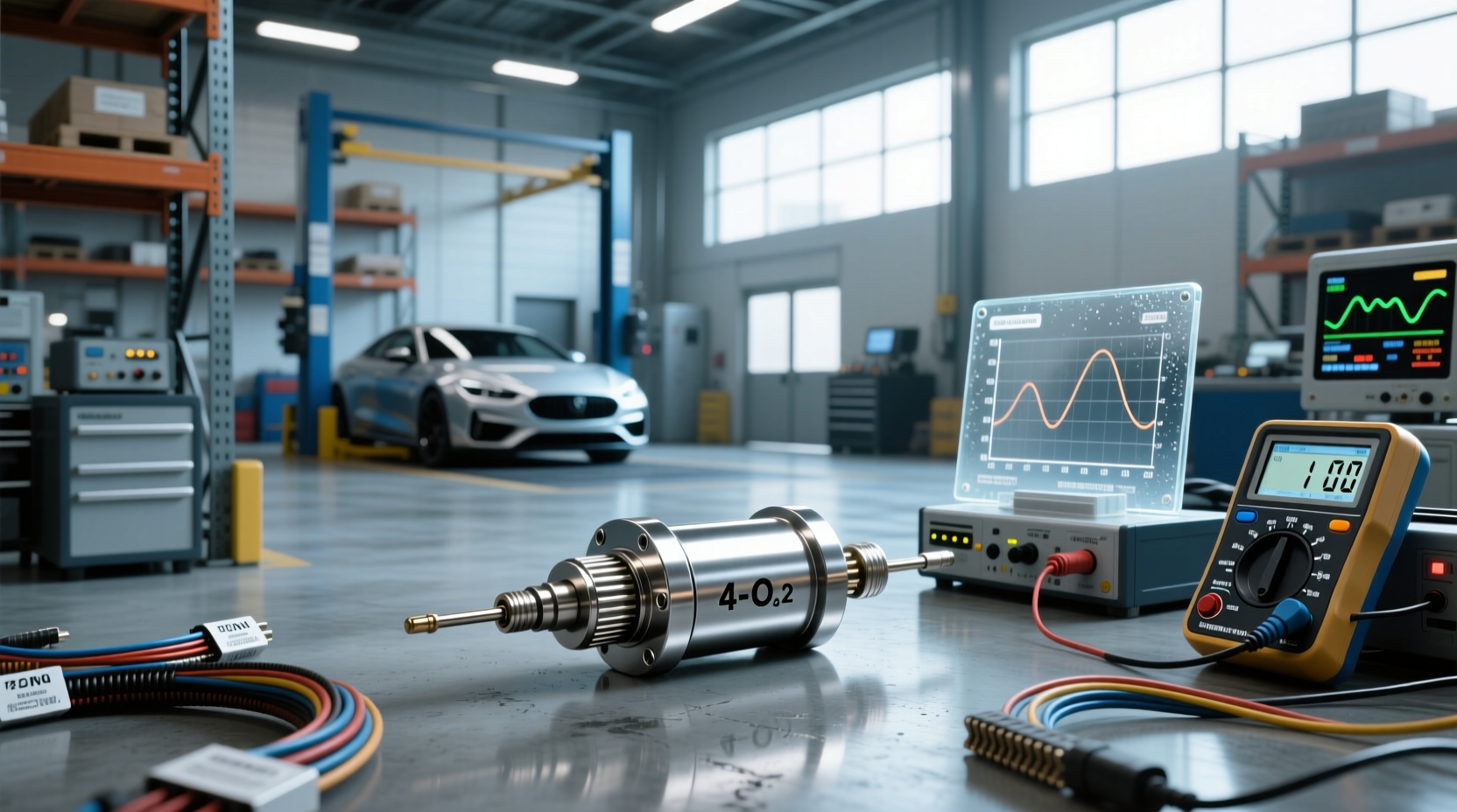
For drivers facing persistent check engine lights due to catalytic converter efficiency codes like P0420 or P0430, a 4 wire O2 sensor simulator offers a technical workaround to stabilize ECU signals—especially in modified, off-road, or older vehicles where emissions compliance isn’t required. Unlike basic spacers or resistor tricks, this device actively mimics the voltage waveform of a post-catalytic oxygen sensor, tricking the engine control unit (ECU) into accepting normal operation without triggering diagnostic trouble codes. This guide breaks down exactly how these simulators function, their practical applications, limitations, and what you should know before installing one.
Understanding the Role of Oxygen Sensors in Vehicle Emissions
Oxygen sensors (also known as lambda sensors) are critical components in modern fuel-injected engines. They monitor the amount of oxygen in exhaust gases and provide real-time feedback to the ECU, which adjusts the air-fuel mixture for optimal combustion efficiency and reduced emissions 1.
Most vehicles use two types of O2 sensors:
- Upstream sensors: Located before the catalytic converter, they help fine-tune fuel trims.
- Downstream sensors: Positioned after the catalyst, their primary role is to verify that the converter is reducing harmful emissions effectively.
The downstream sensor’s signal should be relatively stable compared to the fluctuating upstream signal. If the ECU detects too much fluctuation from the rear sensor—indicating poor catalytic efficiency—it logs a fault code such as P0420 (Catalyst System Efficiency Below Threshold Bank 1).
Why Use a 4 Wire O2 Sensor Simulator?
When the catalytic converter fails or is removed (common in performance builds or off-road vehicles), the downstream O2 sensor no longer receives filtered exhaust gas. As a result, its readings resemble those of the upstream sensor, prompting the ECU to flag inefficiency.
A 4 wire wideband O2 sensor simulator addresses this by generating a steady, simulated output signal between 0.2V and 0.8V—mimicking a functioning catalytic converter. This prevents the check engine light from illuminating and avoids potential drivability issues caused by incorrect fuel mapping.
Common scenarios include:
- 🚗 Vehicles with deleted or gutted catalytic converters for weight reduction or improved exhaust flow.
- 🔧 Dyno tuning or diagnostics where temporary bypassing of post-cat monitoring is needed.
- 🛠️ Off-road-only rigs not subject to emissions testing requirements.
- 📉 Avoiding recurring P0420/P0430 codes on high-mileage vehicles with borderline-efficient cats.
How Does a 4 Wire O2 Sensor Simulator Work?
Unlike simple resistor-based 'dummy' sensors, a true 4 wire O2 sensor emulator replicates the dynamic behavior expected by the ECU. Here's how it functions:
The four wires typically correspond to:
- Signal wire (output): Carries the simulated voltage to the ECU.
- Reference ground: Provides a clean return path for the signal.
- Heater power (+): Draws power to maintain internal circuit stability.
- Heater ground (-): Completes the heater circuit.
Inside the simulator, an integrated circuit generates a controlled analog voltage output that emulates the slow-switching pattern of a healthy downstream O2 sensor. Some advanced models allow adjustable voltage ranges or switching frequencies via potentiometers, making them compatible with various makes including Toyota, Ford, GM, and Subaru.
This differs significantly from passive solutions like O2 sensor spacers, which merely delay sensor exposure to exhaust flow but don't alter signal output.
Differences Between 2-Wire, 4-Wire, and Wideband Simulators
Not all O2 sensor simulators are created equal. Understanding wiring configurations helps avoid compatibility issues.
| Simulator Type | Wires | Functionality | Best For |
|---|---|---|---|
| 2-wire dummy sensor | Signal + Ground | Fixed resistor; limited accuracy | Basic bypass, older vehicles |
| 4-wire narrowband simulator | Signal, ref ground, heater +, heater - | Active signal generation with heater circuit support | Modern gasoline engines, post-cat simulation |
| Wideband O2 simulator | Often 5–6 wires | Mimics broadband lambda sensors used in direct injection systems | Performance tuning, diesel applications |
Using a 2-wire solution on a 4-wire system may lead to heater circuit faults or unstable simulation. Always match the simulator type to your vehicle’s sensor configuration.
DIY vs. Pre-Built 4 Wire O2 Sensor Simulators
Many enthusiasts opt to build their own O2 sensor simulator circuit using resistors, capacitors, and operational amplifiers. A common design involves creating a low-frequency oscillator that outputs a square wave smoothed into a pseudo-analog signal.
A basic version might include:
- 🔋 12V power drawn from the O2 sensor harness heater circuit
- 🔌 1MΩ resistor and 1µF capacitor for timing
- ⚙️ Op-amp or 555 timer IC to generate pulse
- 🎛️ Potentiometer to adjust output voltage (e.g., 0.45V baseline)
Tutorials on platforms like Instructables and Reddit communities such as r/MechanicAdvice detail step-by-step builds 2. However, DIY units lack calibration precision and long-term reliability compared to commercial versions.
Pre-built simulators often come in compact metal housings, pre-calibrated for specific voltage ranges (e.g., 0.2V–0.8V tunable), and include waterproof connectors. These are easier to install and more consistent across temperature changes.
Legal and Environmental Considerations
While technically feasible, using an O2 sensor simulator bypass raises important legal questions.
In the United States, tampering with emission controls—including disabling or deceiving oxygen sensors—is prohibited under the Clean Air Act, even if the vehicle passes visual inspection 3. Violations can result in fines, failed inspections, or voided warranties.
However, enforcement varies:
- 📍 California and states following CARB regulations strictly prohibit any modification that disables emissions equipment.
- 📍 States without mandatory smog checks may not detect the issue unless a mechanic performs a deep scan.
- 🌍 Off-road vehicles registered as non-highway-use are generally exempt from these rules.
Always verify local laws before installation. Even if undetected, removing catalytic converters increases NOx and hydrocarbon emissions, contributing to air pollution.
Installation Tips and Common Pitfalls
Installing a post-cat O2 sensor simulator requires careful attention to wiring and placement.
✅ Best Practices:- Use OEM-style connectors or soldered joints with heat shrink tubing.
- Mount the simulator in a protected area away from direct heat sources.
- Double-check polarity when tapping into heater circuit power.
- Test with an OBD2 scanner to confirm no new codes appear.
- Assuming all simulators work universally—some ECUs monitor response time or heater duty cycle.
- Ignoring reference ground connections, leading to erratic signals.
- Using cheap clones with inconsistent output that still trigger P0130-series codes.
- Installing on upstream sensors, which disrupts fuel trim calculations.
After installation, monitor short-term and long-term fuel trims via live data. Sudden deviations could indicate improper simulation affecting engine performance.
Alternatives to Using an O2 Sensor Simulator
If legality or reliability is a concern, consider these alternatives:
- 📌 Replace the catalytic converter: High-flow cats preserve performance while maintaining emissions compliance.
- 📌 Use an ECU tune: Custom firmware can disable catalyst efficiency monitoring entirely (requires reflashing).
- 📌 Install a test pipe with a functional O2 bung: Allows removal of the cat while retaining sensor presence.
- 📌 Go module or flash programmer: Devices like HP Tuners or Cobb Accessport offer permissive maps for modified exhausts.
Each option has trade-offs in cost, complexity, and regulatory compliance. An ECU reflash is more permanent and seamless than hardware simulators but requires specialized tools.
Vehicle-Specific Compatibility Notes
Compatibility depends heavily on make, model, and ECU logic.
For example:
- 🔹 Toyota trucks and SUVs (e.g., Tundra, 4Runner): Often respond well to adjustable 4-wire simulators due to predictable O2 signal interpretation.
- 🔹 Ford F-150 with modular V8s: May require precise voltage regulation; some report success with Magnum or S03-branded units.
- 🔹 Subaru boxer engines: Dual-exhaust setups may need two simulators unless only one bank is modified.
- 🔹 Diesel applications: Require different strategies due to urea injection (SCR) and DPF monitoring.
Before purchasing, search forums like TundraTalk.net or FordF150.net for user-reported results with specific simulator models.
Testing and Validation After Installation
Once installed, validate functionality using an OBD2 scanner capable of reading live sensor data.
📊 What to Check:- Is the simulated sensor showing a steady voltage between 0.4V and 0.6V?
- Are STFT and LTFT values within ±10%?
- Has the MIL (Malfunction Indicator Light) stayed off during multiple drive cycles?
- Does the freeze frame data show cleared P0420/P0430 codes?
If the ECU continues logging efficiency faults, the simulator may not be accurately replicating expected behavior—or there could be interference from other sensor inputs.
Long-Term Reliability and Maintenance
While solid-state simulators have no moving parts, exposure to engine bay heat, vibration, and moisture can degrade performance over time.
To maximize lifespan:
- Seal all connections against water intrusion.
- Avoid routing near exhaust manifolds or turbochargers.
- Inspect annually for corrosion or loose terminals.
Some users report failure after 1–2 years due to capacitor degradation in lower-quality units. Investing in a well-constructed simulator improves durability.
Conclusion: Weighing Practicality Against Compliance
A 4 wire O2 sensor signal simulator serves a niche but legitimate purpose in certain automotive modifications. It allows owners of off-road, race, or classic vehicles to eliminate nuisance codes without replacing expensive catalytic converters. However, it’s essential to recognize that this solution masks a condition rather than resolving it—and doing so may violate environmental regulations depending on jurisdiction.
Before proceeding, evaluate your usage scenario, local laws, and long-term goals. For track-only or trail-driven vehicles, a simulator can simplify maintenance. For daily drivers in regulated areas, upgrading to a high-flow catalytic converter or getting a proper tune remains the responsible choice.
Frequently Asked Questions
- Can I use a 4 wire O2 sensor simulator on a front (upstream) sensor?
- No. Upstream sensors directly influence fuel trims. Simulating them will cause incorrect air-fuel ratio adjustments, leading to poor performance or damage.
- Is an O2 sensor simulator the same as an O2 spacer?
- No. An O2 spacer physically moves the sensor farther from the exhaust stream, slightly delaying its response. A simulator electronically fakes the signal regardless of position.
- Will a 4 wire O2 sensor emulator work with my diesel engine?
- Generally not. Diesel vehicles rely on additional sensors (DPF, NOx, SCR) beyond O2 monitoring. Bypassing one sensor won’t prevent related fault codes.
- Do I need to disconnect the original downstream O2 sensor?
- Yes. The simulator replaces the sensor’s signal. Leave the physical sensor disconnected or removed to avoid signal conflict.
- Can I pass emissions testing with an O2 sensor simulator installed?
- Unlikely. While the check engine light may stay off, many inspection stations perform loaded-mode tests or use secondary diagnostics that detect missing catalytic function.




 浙公网安备
33010002000092号
 浙B2-20120091-4