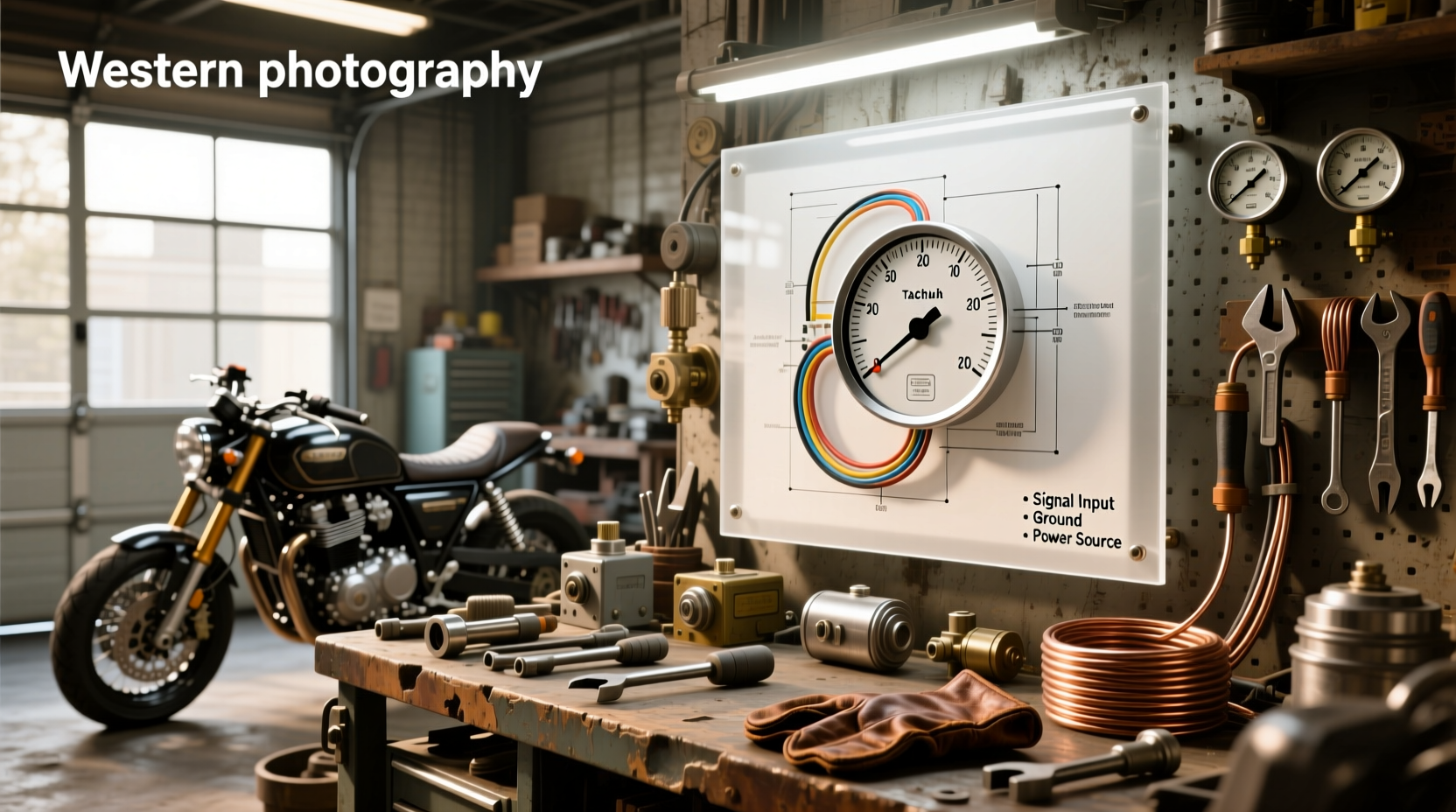
Understanding a motorcycle tachometer wiring diagram is essential for accurate engine performance monitoring. Whether you're upgrading your gauge cluster or installing an aftermarket tach, proper wiring ensures stable RPM readings and prevents electrical issues. This guide breaks down the components, signal types, and correct wiring methods based on ignition system compatibility—helping you avoid common mistakes like incorrect polarity, mismatched sensor types, or grounding errors that lead to erratic behavior or damage.
What Is a Motorcycle Tachometer and Why Wiring Matters
A tachometer measures engine revolutions per minute (RPM), giving riders real-time feedback on engine load, shift points, and operating range. Unlike speedometers, which track wheel movement, tachometers connect directly to the engine’s ignition or crankshaft sensing system. The accuracy of the reading depends heavily on correct wiring setup and signal source selection.
Incorrect wiring can result in no reading, fluctuating RPM display, blown fuses, or even damage to the ECU or instrument cluster. That's why understanding the motorcycle tachometer wiring diagram specific to your bike model and tach type is critical before beginning installation.
Types of Tachometers: Analog vs. Digital, Mechanical vs. Electronic
Tachometers come in several forms, each requiring different wiring approaches:
- Analog (Mechanical): Older motorcycles may use a mechanical cable-driven tach linked to the engine’s camshaft. These are rare today and do not require electrical wiring.
- Analog Electric: Uses a needle display but receives electronic signals from the ignition coil or ECU. Requires power, ground, and signal wires.
- Digital: Displays RPM numerically via LED or LCD. Often part of modern digital dash clusters. May accept multiple input types including inductive, Hall effect, or VR sensors.
Most modern aftermarket tachs are digital and universal, meaning they’re designed to work across various engine types—but only if configured correctly using the appropriate wiring diagram for motorcycle tachometer installation.
Common Signal Sources for Tachometer Input
The key to a functional tach lies in identifying the correct signal source. There are three primary sources used in motorcycle applications:
1. Ignition Coil Negative Terminal (Most Common)
In older motorcycles with contact breaker points or CDI systems, the tachometer typically connects to the negative terminal of the ignition coil. Each time the coil fires, it creates a voltage drop that the tach interprets as one combustion cycle.
This method works well for single- and multi-cylinder engines, though V-twins and inline-fours may need signal conditioning due to uneven firing intervals.
2. Crankshaft Position Sensor (CKP) or Camshaft Sensor
Modern fuel-injected bikes use crankshaft position sensors (often Hall effect or variable reluctance) to determine engine speed. These send a pulsed signal to the ECU, which can also be tapped into for tachometer input.
However, accessing this signal requires careful probing and often involves splicing into factory harnesses. Some digital tachs support direct CKP input, but impedance matching and signal type must align.
3. Dedicated Tach Output from ECU or Harness
Certain OEMs provide a dedicated tach output wire in the main harness—common on touring models or bikes with accessory ports. This is the cleanest option for adding an external tach, as it avoids interference and provides a conditioned square-wave signal.
If available, consult your service manual to locate this wire; otherwise, diagnostic tools or multimeter testing may be required.
Basic Components of a Tachometer Wiring System
A typical tachometer requires at least three connections:
| Wire Color | Function | Voltage/Signal Type |
|---|---|---|
| Red | Power (+12V) | Switched ignition power |
| Black | Ground | Connected to chassis or battery negative |
| White or Yellow | Signal Input | Pulsed ground or positive trigger |
| Blue (optional) | Illumination | Dash lighting circuit |
Always verify wire functions using the manufacturer’s documentation. Miswiring power and signal lines can permanently damage the unit.
Step-by-Step: Installing a Universal Motorcycle Tachometer
Follow these steps to safely install a universal tach using a standard motorcycle tachometer wiring diagram:
Step 1: Choose Mounting Location
Select a spot on the handlebars, triple tree, or dashboard where the tach is visible but doesn’t obstruct controls or instrumentation. Use rubber mounts or vibration-dampening brackets to reduce needle oscillation.
Step 2: Identify Power Source
Tap into a switched 12V circuit (e.g., ignition switch output). Avoid constant hot wires to prevent battery drain. Use a fuse tap or add an inline fuse (typically 1–2A) close to the power source.
Step 3: Establish Ground Connection
Connect the black wire to a clean, unpainted metal surface on the frame or engine. Sand off paint or corrosion for optimal conductivity. Poor grounding causes flickering or false readings.
Step 4: Connect Signal Wire
This is the most crucial step. For coil-negative systems:
- Locate the negative terminal on the ignition coil(s).
- Splice the tach signal wire (usually white) into this line using a solder-and-shrink or insulated crimp connector.
- If running dual coils (e.g., wasted spark), connect to one coil’s negative terminal—do not bridge both unless specified by the tach manual.
For sensor-based systems:
- Determine whether the sensor outputs a Hall effect, VR, or digital signal.
- Use a compatible tach or signal conditioner module if needed.
Step 5: Test Before Finalizing
Reconnect the battery, turn on the ignition, and start the engine. Observe the tach response:
- No movement? Check power, ground, and signal continuity.
- Erratic jumps? Verify grounding and ensure no electromagnetic interference from nearby spark plug wires.
- Double-counting RPM? Some tachs count every spark; on four-stroke twins, this means two sparks per revolution. Adjust calibration or enable divide-by-two mode if available.
Common Wiring Mistakes and How to Avoid Them
Even experienced mechanics make errors when installing tachs. Here are frequent pitfalls:
Mistake #1: Connecting to the Wrong Coil Terminal
Some mistakenly attach the signal wire to the positive coil terminal instead of the negative. This exposes the tach to full 12V constantly, potentially frying internal circuitry.
Mistake #2: Sharing Signal Wires Across Multiple Cylinders Without Buffering
On multi-cylinder engines, combining signals from multiple coils without isolation diodes can cause backfeeding and inaccurate counts. Use a signal combiner module or follow tach-specific guidelines.
Mistake #3: Ignoring Polarity on Digital Tachs
Digital units often have strict polarity requirements. Reversing power and ground can destroy microprocessors instantly.
Mistake #4: Using Non-Shielded Cable Near High-Voltage Sources
Running unshielded signal wires alongside spark plug cables introduces noise. Use twisted-pair or shielded wire and maintain separation.
Aftermarket vs. OEM Tachometers: Compatibility Considerations
Aftermarket tachs offer flexibility but require more setup than OEM units. Universal models must be calibrated for cylinder count and ignition type (two-stroke vs. four-stroke). For example:
- A four-cylinder four-stroke engine produces two sparks per revolution per coil (in wasted spark systems), so the tach must divide the count by two.
- Two-strokes fire once per revolution, so no division is needed.
OEM tachs are pre-programmed for the specific engine and ECU, eliminating configuration needs. However, replacing them can be costly and may require coding via dealer software.
Using a Multimeter or Oscilloscope to Verify Signals
Before connecting a tach, validate the signal using test equipment:
- Multimeter (DC Volts): Set to measure pulses. A functioning coil-negative signal will show rapid dips toward 0V during operation.
- Oscilloscope: Best for analyzing waveform shape. Look for clean square waves (digital) or sinusoidal patterns (VR sensors). Distorted signals indicate poor connections or interference.
This verification step prevents misdiagnosis later and confirms the source is suitable for tach input.
Waterproofing and Vibration Protection
Motorcycles operate in harsh environments. Protect all connections with dielectric grease and heat-shrink tubing. Secure wiring with zip ties away from moving parts and exhaust components. For digital tachs, ensure seals around buttons and displays remain intact.
Legal and Safety Implications of Aftermarket Instrumentation
In some regions, modifying instrumentation may affect vehicle compliance or insurance coverage. While adding a tach is generally acceptable, removing or disabling OEM gauges could violate regulations. Always retain original safety-related indicators (e.g., check engine light, neutral indicator).
When to Consult a Professional
If you're unsure about signal sourcing, lack diagnostic tools, or own a modern ride-by-wire motorcycle with complex CAN bus systems, professional help is recommended. Incorrect probing can set fault codes or disrupt ECU communication.
Frequently Asked Questions (FAQs)
- Can I install a tachometer on any motorcycle?
- Yes, provided you can access a valid RPM signal source such as the ignition coil negative terminal, crankshaft sensor, or ECU output. Universal tachs support most analog and digital inputs, but configuration is required.
- Where is the RPM sensor located on most motorcycles?
- On fuel-injected models, the crankshaft position sensor (RPM sensor) is typically near the crankshaft pulley, stator cover, or transmission area. On carbureted bikes, RPM is often derived from the ignition coil rather than a separate sensor.
- Why is my motorcycle tachometer jumping erratically?
- Erratic readings usually stem from poor grounding, loose connections, electromagnetic interference, or incorrect signal calibration. Check all wiring integrity and ensure the tach is set for the correct cylinder count and engine type.
- Do I need a separate RPM sensor for an aftermarket tach?
- Not always. Many aftermarket tachs use existing signals (like coil negative) and don’t require additional sensors. However, advanced digital systems may need a Hall effect or VR pickup if no suitable signal exists.
- How do I calibrate a universal motorcycle tachometer?
- Calibration involves setting cylinder count, stroke type (2T/4T), and sometimes pulse division ratio. Refer to the user manual—some models use dip switches, others require button sequences during startup.




 浙公网安备
33010002000092号
 浙B2-20120091-4