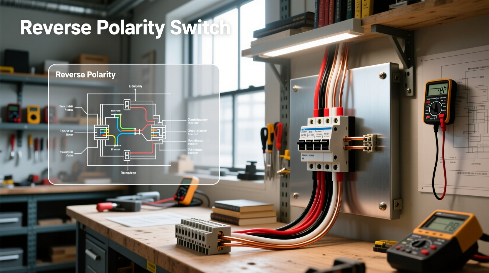
⚡ Understanding how to correctly wire a reverse polarity switch is essential for controlling DC motors in applications like RV stabilizers, winches, boat lifts, and automated systems. A reverse polarity switch wiring diagram helps users visualize how a Double Pole Double Throw (DPDT) switch reverses the direction of current flow by swapping positive and negative connections—allowing a motor to run forward or backward without manual rewiring. This article provides a comprehensive breakdown of reverse polarity switching, including functional principles, correct wiring techniques, safety considerations, and troubleshooting tips—all centered around practical implementation and user safety.
What Is a Reverse Polarity Switch?
A reverse polarity switch is an electrical component designed to change the direction of current flow in a direct current (DC) circuit. It's commonly used to control the rotation direction of permanent magnet DC motors. The most typical configuration uses a Double Pole Double Throw (DPDT) toggle or rocker switch, which has six terminals: two input terminals (positive and negative from the power source), and four output terminals connected in a crossover pattern to the load (usually a motor).
The switch operates on a simple principle: when toggled, it physically swaps the polarity sent to the motor. In one position, Terminal A receives positive voltage while Terminal B gets negative; in the opposite position, the polarities are reversed. This causes the motor shaft to rotate in the opposite direction.
🔧 Most reverse polarity switches used in automotive, marine, and recreational vehicle setups are 3-position: ON-OFF-ON. The center position disconnects the circuit (off), while the two outer positions apply reversed polarity to the motor. These can be either momentary (spring-loaded, returning to center when released) or latching (staying in position until manually switched back).
Why Use a DPDT Switch for Polarity Reversal?
The DPDT switch is ideal for reversing polarity because it controls two separate circuits simultaneously—each pole handles one side of the power line (positive and negative). When the switch is flipped, both poles change their contact paths, effectively crossing the wires.
⚙️ Imagine two parallel switches moving together. One switches the positive wire from Output 1 to Output 2, while the other switches the negative wire from Output 2 to Output 1. This cross-connection flips the voltage across the motor terminals, reversing its direction.
This method avoids the need for complex relays or H-bridge circuits in basic applications and provides a reliable mechanical solution that’s easy to install and troubleshoot.
Understanding the Reverse Polarity Switch Wiring Diagram
A proper reverse polarity switch wiring diagram should clearly show all six terminals of the DPDT switch and how they connect to the power source and motor. Below is a detailed textual explanation followed by a conceptual layout you can replicate.
Terminal Layout of a Standard DPDT Switch
Most DPDT switches have six screw terminals arranged in two rows of three. From left to right:
- Top Row: Terminal 1 (Common A), Terminal 2 (Normally Open A), Terminal 3 (Normally Closed A)
- Bottom Row: Terminal 4 (Common B), Terminal 5 (Normally Closed B), Terminal 6 (Normally Open B)
| Position | Top Row Terminals | Bottom Row Terminals |
|---|---|---|
| Left | 1 - Common A | 4 - Common B |
| Middle | 2 - NO A / 3 - NC A | 5 - NC B / 6 - NO B |
| Right | 3 - NC A / 2 - NO A | 6 - NO B / 5 - NC B |
Step-by-Step Wiring Instructions
Follow these steps to wire a DPDT switch for reverse polarity control:
- Identify Power Source Wires: Locate your 12V or 24V DC power supply. Label the positive (+) and negative (-) leads.
- Connect Power to Common Terminals: Attach the positive wire to Terminal 1 (Common A) and the negative wire to Terminal 4 (Common B).
- Cross-Wire the Motor Connections:
- Connect one motor terminal to Terminal 2 (NO A) and Terminal 5 (NC B).
- Connect the second motor terminal to Terminal 3 (NC A) and Terminal 6 (NO B).
- Verify Insulation & Mounting: Ensure all connections are tight and insulated. Secure the switch in a dry, accessible location.
- Test Operation: Power on the system and toggle the switch. The motor should run in one direction in the up position, stop in the middle (if center-off), and reverse in the down position.
📌 This setup creates an internal 'H' bridge effect through mechanical switching, eliminating the need for electronic controllers in simple directional control tasks.
Common Applications of Reverse Polarity Switches
Reverse polarity switches are widely used in environments where bidirectional motor control is needed without sophisticated electronics. Key use cases include:
- RV Stabilizer Jacks: Control hydraulic or electric jacks that extend and retract using a single motor.
- Winches and Hoists: Allow cable spooling in and out via forward/reverse motor action.
- Boat Anchors and Ramps: Operate lifting mechanisms with reversible motion.
- Model Trains and Robotics: Change travel direction on tracks or robotic arms.
- Solar Panel Trackers: Adjust panel orientation east-west based on sun position.
🏭 In industrial settings, such switches may control conveyor belts, gate openers, or ventilation flaps. Their simplicity makes them durable in harsh conditions where moisture, vibration, or dust could interfere with digital systems.
Safety Considerations When Installing a Reverse Polarity Switch
While the wiring process is straightforward, several safety issues must be addressed:
⚠️ Risk of Short Circuits
If the switch is wired incorrectly—especially if both poles connect positive to positive and negative to negative at the same time—it can create a short circuit between the power source and the motor. This may result in blown fuses, damaged wiring, or fire hazards.
✅ Always double-check connections before powering the circuit. Use a multimeter to test continuity and ensure no unintended paths exist between + and - when the switch is in either ON position.
Fuse Protection
Install an inline fuse close to the battery or power source. Choose a fuse rated slightly above the motor’s maximum draw (e.g., 30A for a 25A motor). This protects against overcurrent situations caused by jams or miswiring.
Proper Wire Gauge Selection
Use appropriately sized wire to handle the motor’s current. For example:
- Up to 10A: 16 AWG
- 10–20A: 14 AWG
- 20–30A: 12 AWG
- Over 30A: 10 AWG or larger
Environmental Protection
If installing outdoors or in wet areas (like on a boat or RV), choose a waterproof DPDT switch rated at least IP67 or IP68. Look for sealed rubber boots or gaskets around the toggle lever to prevent moisture ingress.
Differences Between Momentary and Latching Reverse Polarity Switches
Not all reverse polarity switches behave the same way. Two main types exist:
🔷 Momentary (Spring-Return) Switches
These return to the OFF (center) position when released. They’re ideal for applications requiring temporary activation, such as raising or lowering a jack only while the button is pressed. Prevents accidental continuous operation and overheating.
🔷 Latching (Maintained) Switches
Stay in position after being toggled. Once set to 'up' or 'down', they remain active until manually changed. Useful for long-duration operations but require vigilance to avoid leaving the motor running too long.
👥 Your choice depends on operational needs. For safety-critical or intermittent use, go with momentary. For convenience in sustained movement, latching may be preferable—but always pair it with a limit switch or timer if possible.
Troubleshooting Common Issues
Even with correct installation, problems can arise. Here are frequent issues and solutions:
❌ Motor Doesn’t Run in Either Direction
- Check fuse and battery voltage.
- Verify all wire connections are secure.
- Test switch continuity with a multimeter in each position.
❌ Motor Only Runs in One Direction
- Inspect whether one pole of the switch is faulty or not making contact.
- Confirm that crossed wires (Terminals 2→5 and 3→6) are properly linked.
- Ensure the motor itself isn’t internally damaged.
❌ Sparks or Overheating
- Check for loose terminals causing arcing.
- Verify wire gauge matches current load.
- Replace switch if contacts are worn or pitted.
❌ Switch Feels Loose or Unresponsive
- Mounting hardware may be loose—tighten nuts securely.
- Switch mechanism may be worn out—replace if necessary.
Reverse Polarity vs. AC Outlet Polarity: Don’t Confuse Them
❗ A common point of confusion arises between reverse polarity in DC motor control and reversed polarity in AC household outlets. While both involve incorrect wiring of hot and neutral lines, they are entirely different contexts.
In AC systems, reversed polarity means the hot wire is connected where the neutral should be (and vice versa), creating shock risks even when devices are off. This is unrelated to DPDT motor reversal and requires correction by a qualified electrician.
⚡ Our focus here is strictly on low-voltage DC circuits used in vehicles, trailers, and equipment—not residential AC wiring.
Can You Use Relays Instead of a Mechanical Switch?
Yes. Some advanced installations use two SPDT relays or a pre-built H-bridge relay module to achieve the same polarity reversal function. Advantages include remote mounting, integration with control panels, and compatibility with automation systems.
However, relays add complexity, require additional control signals, and depend on auxiliary power. For most DIY users, a physical DPDT switch remains simpler, more intuitive, and easier to diagnose.
DIY Tips for Building Your Own Setup
🛠️ If building your own reverse polarity control system, consider these best practices:
- Label All Wires: Use colored tape or shrink tubing to mark +, -, M1, M2 for clarity.
- Use Terminal Blocks: Make future maintenance easier by grouping connections.
- Add Indicator Lights: Install small LEDs to show when power is applied in each direction.
- Secure the Switch: Vibration can loosen connections—use lock washers and anti-vibration mounts.
- Keep Spare Fuses: Always carry replacements in mobile applications.
When Not to Use a Reverse Polarity Switch
While effective, this method isn't suitable for every scenario:
- High-Frequency Reversals: Frequent switching under load wears out mechanical contacts.
- Precision Speed Control: Does not regulate speed—only direction.
- Induction Motors: Only works with permanent magnet DC motors. AC or brushless DC motors require electronic drivers.
- Locked Rotor Conditions: Never hold the switch engaged if the motor is jammed—this draws excessive current.
Final Thoughts: Mastering Reverse Polarity Control
Mastering the reverse polarity switch wiring diagram empowers you to take full control of DC motor direction in a wide range of practical applications. Whether you're installing an RV jack, marine lift, or custom automation project, understanding how a DPDT switch reverses polarity ensures safe, efficient, and reliable operation.
The key lies in correct wiring: connecting power to the common terminals and implementing the crossover connection to the motor. Combine this with proper fusing, wire sizing, and environmental protection, and you’ll build a robust system that lasts.
Remember, electricity demands respect. Always de-energize the circuit before working on it, verify connections with testing tools, and never bypass safety features for convenience.
Frequently Asked Questions
- ❓ What does a reverse polarity switch do?
- A reverse polarity switch changes the direction of current flow in a DC circuit, typically to reverse the rotation of a motor. It uses a DPDT switch to swap the positive and negative connections to the motor terminals.
- ❓ How do you wire a DPDT switch for motor reversal?
- Connect the power source to the two common terminals (1 and 4). Then cross-connect the motor leads: link terminal 2 (NO A) to terminal 5 (NC B), and terminal 3 (NC A) to terminal 6 (NO B). This creates reversed polarity in each switch position.
- ❓ Is reversed polarity dangerous?
- In DC motor control, reversed polarity is intentional and safe when done correctly. However, in AC household wiring, reversed polarity can create shock hazards and must be corrected immediately.
- ❓ Can I use a single pole switch to reverse motor direction?
- No. A single pole switch cannot reverse polarity because it only interrupts one side of the circuit. You need a double pole switch to simultaneously reverse both positive and negative lines.
- ❓ Where can I find a reverse polarity switch wiring diagram?
- You can find accurate diagrams in this article, manufacturer datasheets, or technical guides from reputable electrical engineering resources. Always confirm terminal labels match your specific switch model before wiring.




 浙公网安备
33010002000092号
 浙B2-20120091-4