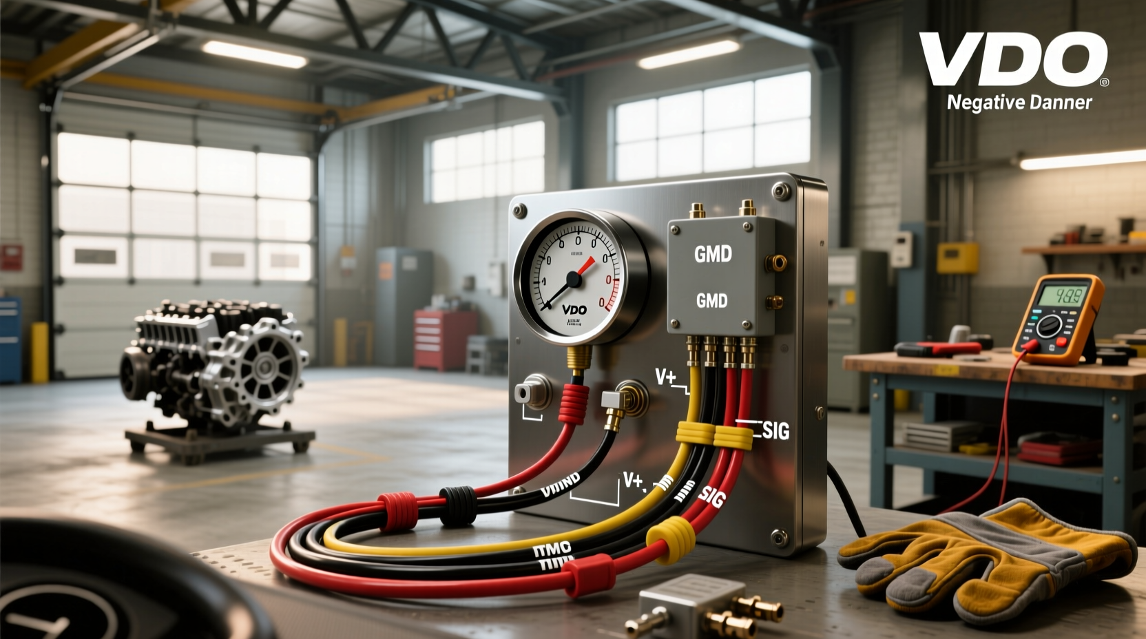
Installing a VDO tachometer properly starts with understanding the correct vdo tachometer wiring diagram for your specific engine type and gauge model. Whether you're upgrading an older vehicle, installing a new marine instrument panel, or replacing a faulty unit, getting the wiring right is essential for accurate RPM readings and long-term reliability. This comprehensive guide walks through every aspect of VDO tachometer wiring—including analog vs. programmable models, ignition system compatibility, signal sources, grounding best practices, and troubleshooting common issues—so you can complete the job confidently and avoid costly mistakes.
Why Accurate VDO Tachometer Wiring Matters
A tachometer measures engine revolutions per minute (RPM), providing critical feedback during operation. When improperly wired, it may display erratic readings, fail to start, or damage sensitive internal circuitry. Many users searching for a vdo tachometer wiring diagram pdf are trying to resolve such problems after incorrect installation. The key challenge lies in matching the tachometer’s input requirements to the engine's ignition system—whether that’s points-based, electronic ignition, diesel, or marine—and ensuring proper power, ground, and signal connections.
VDO offers multiple tachometer series—such as the Vision, Cockpit International, and Programmable lines—each with different wiring needs. Some models require only three wires (power, ground, signal), while others need additional connections for lighting, shift lights, or memory functions. Understanding these differences before beginning installation prevents confusion and ensures compatibility.
Understanding VDO Tachometer Types and Their Wiring Needs
VDO manufactures several categories of tachometers designed for various applications, including automotive, marine, industrial, and aviation engines. Each has unique wiring configurations based on functionality and signal processing.
Analog VDO Tachometers ⚙️
Analog tachometers like the VDO 333-156 or 333-158 series use a mechanical movement driven by electrical pulses from the ignition system. These typically connect via three terminals:
- I+ (Ignition Plus): 12V power from switched ignition source
- S (Signal): Pulse input from coil negative terminal or distributor
- GND (Ground): Direct connection to chassis or battery negative
These units do not require programming and rely solely on consistent pulse signals. They work well with gasoline engines using 1-, 4-, 6-, or 8-cylinder distributors. The number of pulses per revolution varies by engine type, so selecting the correct scale (e.g., 0–4000 RPM, 0–8000 RPM) is important.
Programmable Digital Tachometers 🔧
Modern VDO programmable tachometers—like the A2C59501504 or J/109 class models—offer adjustable settings for cylinder count, idle speed, redline, and hourmeter tracking. These often include extra features such as peak RPM recall, shift lights, and memory retention.
Wiring these involves more than just basic power and signal:
- B+: Constant 12V supply (for memory)
- IGN: Switched 12V ignition power
- SGND: Signal ground
- TACH OUT: Pulse output (if daisy-chaining)
- LIGHTING: Dash light dimming circuit
- SHIFT: Output for external shift light
Before connecting, consult the programmable vdo tachometer manual to configure cylinder count and signal type. Misprogramming can lead to inaccurate readings even if wiring appears correct.
Marine and Diesel-Specific Models 🌊
VDO also produces tachometers tailored for marine environments (e.g., VDO Marine Cockpit series) and diesel engines. Marine units often have waterproof housings and corrosion-resistant connectors. Diesel tachometers usually accept signal from an alternator ‘W’ terminal or magnetic pickup sensor rather than an ignition coil, since diesel engines lack spark plugs.
For example, a vdo tachometer for diesel engine might require:
- Connection to the alternator stator output (W terminal)
- Use of a signal conditioner module if pulse count doesn’t match gauge expectations
- Dedicated marine-grade wiring harnesses to resist moisture
Always verify whether your engine produces AC or DC signal and adjust accordingly.
Step-by-Step VDO Tachometer Wiring Process
Follow this structured approach to ensure safe and accurate installation.
Step 1: Identify Your Tachometer Model and Specifications ✅
Check the model number printed on the back of the gauge or in documentation. Common examples include:
- VDO 333-156 – 4000 RPM Analog
- VDO 333-158 – 6000 RPM Programmable
- VDO A2C3833030001 – 4000 RPM with Shift Light
Confirm voltage rating (almost always 12V), RPM range, and cylinder compatibility. Use manufacturer resources or product datasheets to access the official vdo tachometer wiring diagram.
Step 2: Locate the Correct Signal Source 🔍
The accuracy of your tachometer depends entirely on receiving clean, consistent pulses. Choose the appropriate signal source based on engine type:
| Engine Type | Signal Source | Pulse Notes |
|---|---|---|
| Gasoline (Points) | Negative terminal of ignition coil | One pulse per spark; matches cylinder count |
| Gasoline (Electronic) | ECU tach output or coil pack signal | May require adapter for COP systems |
| Diesel | Alternator W terminal or magnetic pickup | AC signal; frequency proportional to RPM |
| Marine Outboard | Engine control module (ECM) tach output | Consult OEM manual for pinout |
Avoid tapping into random wires without verification. Use a multimeter or oscilloscope to confirm signal presence and type (AC/DC).
Step 3: Prepare Power and Ground Connections ⚡
Connect the tachometer to a reliable 12V switched ignition source (IGN) for normal operation. For programmable models, also connect a constant B+ line to maintain settings when the engine is off.
Grounding is equally crucial. Use a dedicated grounding point near the dashboard or directly to the battery negative terminal. Avoid sharing grounds with high-draw accessories like fans or pumps, which can introduce noise.
Step 4: Connect the Tach Signal Wire 📎
Run the signal wire from the identified source to the 'S' terminal on the tachometer. Keep this wire away from high-current cables (like starter or alternator leads) to reduce electromagnetic interference. Shielded cable is recommended in noisy electrical environments.
If using an adapter (e.g., for COP ignition systems), install it between the signal source and the tachometer according to its instructions.
Step 5: Test Before Final Mounting 🔧
Temporarily power the tachometer and crank the engine to verify needle movement. At idle, expect steady reading around 600–1000 RPM depending on engine. If the needle jumps erratically or stays at zero, recheck connections and signal source.
Common Wiring Mistakes and How to Avoid Them ❗
Even experienced mechanics make errors when installing tachometers. Here are frequent pitfalls:
- Using wrong signal source: Connecting to positive coil instead of negative causes no response or damage.
- Incorrect cylinder setting: Setting a 4-cylinder tach to 6-cylinder doubles the displayed RPM.
- Poor grounding: Floating ground leads to flickering or drifting readings.
- Ignoring lighting circuit: Not connecting the illumination wire results in non-functional backlighting.
- Overlooking memory requirements: Programmable units lose settings without constant B+ power.
To prevent these, always refer to the exact vdo tachometer wiring diagram pdf for your model. Do not assume all VDO gauges wire the same way.
Troubleshooting a Non-Working VDO Tachometer 🛠️
If your tachometer isn't functioning, follow this diagnostic checklist:
- Verify power at IGN and B+ terminals with a voltmeter (should read ~12V with key ON).
- Test ground continuity between GND terminal and battery negative (should be near 0 ohms).
- Check signal input using a test light or multimeter in frequency mode.
- Inspect fuse and inline protection—some installations include a fuse on the power line.
- Ensure correct programming (for digital models): reset and reconfigure cylinder count.
If all checks pass but the gauge still fails, the internal electronics may be damaged—possibly due to reverse polarity or voltage spike. Consider professional repair or replacement.
Finding Reliable VDO Tachometer Resources Online 🔗
While many sites offer generic vdo tachometer wiring diagram images, only manufacturer or authorized distributor documentation should be trusted. Useful sources include:
- gaugesvdo.com – Official U.S. distributor with product specs and support
- vdo-instruments.com – Technical details and performance model data
- J/109 Class Association PDF 1 – Real-world installation guide for programmable units
Avoid relying solely on forum posts or YouTube videos unless they cite official documentation.
When to Seek Professional Help 🧰
If you’re unsure about signal compatibility, working with modern CAN-bus systems, or integrating the tach into a custom dash, consulting a professional automotive electrician is wise. Miswiring can affect ECU communication or trigger error codes in advanced vehicles.
Conclusion: Getting It Right the First Time
Successfully installing a VDO tachometer hinges on using the correct vdo tachometer wiring diagram for your specific model and engine setup. Take time to identify your gauge type, locate the proper signal source, and make clean, secure connections. Refer to authoritative technical documents—not guesswork—to ensure lasting performance. With careful planning and attention to detail, you can achieve precise RPM monitoring across automotive, marine, or industrial applications.
Frequently Asked Questions
- How do you hook up a VDO tachometer?
- Connect the I+ or IGN terminal to switched 12V power, GND to chassis ground, and S to the ignition coil’s negative terminal (gasoline engines) or alternator W terminal (diesel). For programmable models, also connect B+ for memory and configure cylinder count.
- Are VDO gauges any good?
- Yes, VDO is a reputable German brand known for precision engineering and durability in harsh environments. Their tachometers are widely used in OEM and aftermarket applications across automotive, marine, and industrial sectors.
- What does VDO mean in cars?
- VDO stands for Versuchswerkstätten für Drahtloser Ortsfunk, originally a German instrumentation company now part of Continental AG. In cars, VDO refers to their line of gauges, sensors, and dashboard instruments.
- Can I use a VDO tachometer with a modern coil-on-plug ignition system?
- Yes, but you may need a signal converter or adapter module to generate a compatible tach signal, as COP systems don’t provide a direct negative pulse like traditional coils.
- Where can I find a VDO tachometer wiring diagram PDF?
- Official diagrams are available from authorized distributors like gaugesvdo.com, vdo-instruments.com, or through technical documents such as those provided by the J/109 Class Association 1.




 浙公网安备
33010002000092号
 浙B2-20120091-4