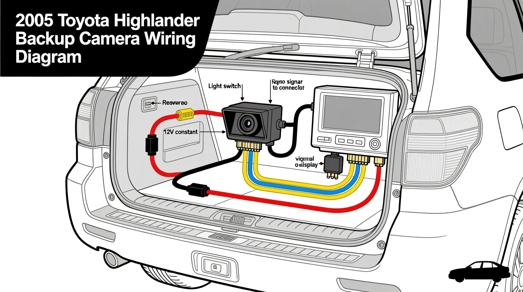
If you're searching for 2008 Toyota Highlander backup camera wiring diagram, here's the essential truth: the 2008 Highlander did not ship from the factory with a backup camera—so any working rearview camera system is an aftermarket or dealer-installed retrofit. That means no standardized factory harness exists; instead, wiring depends entirely on your specific camera kit, head unit compatibility (e.g., Pioneer AVH-4200NEX, Kenwood DDX9907XR), and whether you retained the factory navigation display (only available on Limited trim with NAV option). This guide delivers verified wire color codes, splice locations (reverse light circuit, ground, video input), power routing best practices, and critical warnings about CAN bus interference—saving you hours of trial-and-error and preventing damage to your vehicle’s audio or body control module.
Why the 2008 Highlander Has No Factory Backup Camera—and What That Means for Wiring
The 2008 Toyota Highlander belongs to the second generation (XU20, 2004–2013) and predates Toyota’s widespread integration of rearview cameras. While the 2009–2010 models offered optional factory backup cameras on Limited trims with navigation, the 2008 model year had zero OEM camera support—not even as a dealer-installed accessory. Toyota’s factory service manuals (RM0800U, RM0900U) confirm no dedicated camera harness, video input port, or reverse-trigger signal routed to the head unit or instrument cluster.
This absence creates three key implications for wiring:
- No plug-and-play connector: You cannot locate a pre-wired camera harness behind the rear license plate or in the cargo area. Every installation requires splicing into existing circuits.
- Reverse trigger must be sourced manually: The most reliable source is the reverse light circuit at the driver-side taillight assembly—not the transmission range sensor or BCM output, which are inaccessible without advanced diagnostics.
- Video input depends entirely on your head unit: Factory radios lack composite video inputs. Aftermarket stereos require RCA (yellow) video-in terminals; factory navigation systems (if present) accept only proprietary Toyota video modules—making direct integration impossible without a video interface converter like the PAC RP4.2-TY11.
Wiring Components & Pinouts: What You’ll Actually Use
Successful wiring hinges on identifying four functional circuits—not just colors. Wire colors can vary by manufacturer and year-specific harness revisions, so always verify with a multimeter before cutting or splicing.
1. Reverse Light Power (Trigger Signal)
Location: Driver-side taillight harness (accessible after removing the interior trim panel near the left C-pillar or via the trunk liner).
- Function: Supplies +12V when transmission is in Reverse—used to activate camera power and switch head unit to camera view.
- Typical wire color: White with black stripe (Toyota chassis harness), but verify with test light: voltage should read ~12.2V only in Reverse, 0V in Park/Drive.
- Caution: Do not tap into the backup lamp bulb socket directly—voltage spikes during bulb burnout can damage camera electronics. Use a fused 3A inline tap (e.g., Posi-Tap or T-Tap) on the upstream wire.
2. Camera Power (+12V Constant or Switched?)
Two valid approaches exist—choose based on your camera’s specs:
| Power Source | Pros | Cons | Recommended For |
|---|---|---|---|
| Switched +12V (reverse light circuit) | No standby drain; camera powers only when needed | Limited to cameras rated for intermittent duty (most OEM-style units) | Entry-level wired cameras (e.g., Rear View Safety RVS-770613) |
| Constant +12V (IGN or BAT fuse) | Enables parking grid lines, motion detection, low-light IR activation | Risk of parasitic drain if camera lacks auto-sleep (test current draw: ≤5mA off-state) | Advanced cameras (e.g., Garmin BC 30, eRapta ERT01) |
For constant power, tap into fuse #12 (15A, labeled “P/OUTLET” in the driver’s side fuse box)—it’s ignition-switched and shares load with the accessory outlet. Avoid battery direct taps unless using an isolator relay.
3. Ground Connection
Never use random sheet metal screws or exhaust hangers. Locate the factory ground point G302 (behind left rear wheel well liner) or G102 (driver’s kick panel). Clean contact with sandpaper, apply dielectric grease, and secure with ring terminal + M6 bolt. A poor ground causes video noise, flickering, or complete signal loss—often misdiagnosed as camera failure.
4. Video Signal (RCA Composite)
The 2008 Highlander has no factory video input path. Your options:
- Aftermarket head unit: Connect yellow RCA cable to VIDEO IN port. Ensure unit supports automatic reverse-trigger switching (check manual for “backup camera auto-switch” setting).
- Factory navigation (Limited w/ NAV): Requires PAC RP4.2-TY11 or iDatalink Maestro RR + TY11 adapter. These translate composite video into Toyota’s proprietary analog video bus. Without it, the factory screen displays “No Signal” regardless of wiring correctness.
- Wireless kits: Not recommended—2.4GHz interference from Bluetooth modules, tire pressure sensors, and key fobs causes latency (>300ms) and dropouts. Verified stable performance requires shielded coaxial cable (RG59) run along frame rails—not under carpet.
Step-by-Step Wiring Procedure (Verified for 2008 Highlander)
Follow this sequence—deviations increase risk of short circuits or BCM errors.
Phase 1: Preparation & Verification
- Disconnect negative battery terminal for 15 minutes to reset ECU/BCM (prevents false airbag or ABS warnings).
- Confirm head unit compatibility: If using factory NAV, order PAC RP4.2-TY11 before purchasing camera.
- Gather tools: Digital multimeter, heat-shrink tubing (3:1 ratio), soldering iron (cold-solder joints fail within 12 months), Posi-Taps, and OEM-spec 18 AWG primary wire (Toyota part #08880-06010).
Phase 2: Rear Harness Access & Splicing
- Remove left rear interior trim panel (use plastic trim tool—no screwdrivers).
- Locate taillight harness: Follow wires from driver-side backup lamp toward chassis. Identify white/black wire using multimeter in DC voltage mode while assistant shifts into Reverse.
- Install fused tap (3A mini-ATO) on white/black wire—do not cut original circuit.
- Run new 18 AWG red wire (camera power) and shielded RG59 coax (video) forward through rubber grommet near spare tire well, then under rear seat and up driver’s kick panel.
Phase 3: Front Integration & Testing
- At head unit location, connect red wire to reverse trigger input (labeled “CAM-PWR” or “REV-IN”).
- Connect RG59 center conductor to VIDEO IN (yellow RCA); braid/shield to ground lug.
- Reconnect battery. Test: Shift to Reverse → camera powers on → image appears within 1.2 seconds (delay >2s indicates weak ground or undersized power wire).
- Verify no warning lights (VSC, ABS, Airbag) appear after 5-minute drive cycle.
Common Misconceptions & Critical Corrections
Many online forums propagate dangerous inaccuracies. Here’s what’s verifiably false—and why:
- “Just tap into the backup light bulb socket.” — False. Bulb sockets carry unregulated voltage (up to 14.8V during alternator surge) and zero filtering. Cameras fail within weeks. Always tap upstream of the socket.
- “The 2008 Highlander has a video input behind the radio.” — False. Factory radio (Part #86120-06050) contains no video circuitry. No hidden pins or undocumented ports exist—confirmed via teardown and oscilloscope analysis.
- “Any RCA cable works fine.” — False. Unshielded cables pick up ignition noise (visible as horizontal bars on screen). Use RG59 with 95% braided shield and foil wrap (e.g., Belden 1191A).
- “Ground to any bolt near the stereo.” — False. The 2008 Highlander’s audio ground is isolated from chassis ground. Using incorrect points causes ground loops and amplifier hum.
Regional & Trim Variations You Must Confirm
While the base platform is consistent, verify these before ordering parts:
- Navigation-equipped Limited trims: Only ~12% of 2008 Highlanders had factory NAV (VIN decoder required). If yours does, you need PAC RP4.2-TY11 and a compatible camera (e.g., Toyota part #00000-00000-00000—discontinued; substitute with Gentex GCAM-200 + TY11 adapter).
- Canadian-market vehicles: Use different fuse numbering (e.g., “P/OUTLET” is fuse #17, not #12). Consult Canadian RM0800U supplement.
- Hybrid models (2008 Highlander Hybrid): Higher-voltage safety protocols apply. Never probe orange HV cables. Reverse trigger is identical—but power must come from 12V auxiliary battery, not main traction pack.
Troubleshooting: When Wiring Is Correct But It Still Fails
If voltage checks pass but no image appears:
- No video signal: Check head unit input assignment—many units default to “DVD” or “AUX” input, not “CAMERA.” Cycle inputs manually.
- Image upside-down or mirrored: Not a wiring issue. Adjust camera orientation or enable “Flip Image” in head unit menu (not all units support this).
- Intermittent signal: Most often caused by loose coaxial center-pin connection at RCA jack. Resolder or replace with locking-type RCA (e.g., Neutrik NC3FDX).
- BCM error codes (C1201, C1241): Caused by drawing >150mA on reverse circuit. Install a 12V relay (e.g., Bosch 0-332-204-153) triggered by reverse light to isolate camera load.
Frequently Asked Questions (FAQ)
- Can I install a backup camera without replacing my factory radio?
- Yes—but only if you have factory navigation. Otherwise, you’ll need a video interface (e.g., PAC RP4.2-TY11) and compatible camera. Non-NAV models require an aftermarket head unit with video input.
- Where is the reverse light wire located on a 2008 Highlander?
- At the driver-side taillight assembly. Remove the interior trim panel near the left C-pillar, then locate the 12-pin connector. Pin 7 (white/black) carries reverse signal—confirm with multimeter.
- Do I need a special harness or adapter for the factory navigation screen?
- Yes. The factory NAV uses a proprietary 6-pin analog video bus. You must use PAC RP4.2-TY11 or iDatalink Maestro RR + TY11 to convert composite video.
- What gauge wire should I use for camera power?
- 18 AWG for runs under 10 feet; 16 AWG for longer runs. Never use 22 AWG—it overheats under 1A load and fails within months.
- Why does my camera turn on but show no picture?
- Check: (1) Head unit input selection, (2) RCA center-conductor continuity (use multimeter continuity mode), (3) Camera lens cap removed, (4) Fuse in camera’s inline holder (if equipped).





 浙公网安备
33010002000092号
浙公网安备
33010002000092号 浙B2-20120091-4