Installing a quick shifter on your motorcycle is a high-impact upgrade that enables clutchless upshifts—improving acceleration, reducing shift time by up to 0.15 seconds, and enhancing track-day consistency. This step-by-step quick shifter installation guide for modern fuel-injected motorcycles covers everything from compatibility verification and wiring pinouts to ECU calibration and real-world validation—no dealership visit required in most cases. You’ll learn how to avoid common pitfalls like incorrect sensor alignment, mismatched firmware versions, or overlooked CAN bus termination resistors. Whether you ride a Yamaha R1, Kawasaki ZX-14R, Ducati Panigale, or KTM 1290 Super Duke, this guide delivers verified procedures used by professional tuners and seasoned DIY mechanics across North America and Europe.
Why Install a Quick Shifter? Understanding the Real-World Benefits
A quick shifter (QS) is an electronic device that momentarily cuts ignition or fuel during an upshift, allowing seamless gear changes without using the clutch. Unlike basic aftermarket kits from the early 2000s, today’s systems integrate with OEM ECUs via CAN bus or analog signals—and many support bi-directional shifting (up/down), launch control, and auto-blip functionality. The primary benefit isn’t just convenience: racers gain measurable lap-time advantages; street riders reduce wrist fatigue and improve safety during aggressive acceleration; and owners of high-torque liter-class bikes prevent driveline shock that can accelerate transmission wear.
However, benefits depend entirely on correct installation and calibration. A misaligned microswitch or improperly configured cut duration can cause hesitation, stalling, or even engine misfires under load. That’s why this guide emphasizes validation over assumption—every step includes verification checkpoints, not just instructions.
Before You Begin: Critical Pre-Installation Checks
Never open your fairing until you’ve completed these five non-negotiable checks:
- OEM Compatibility: Confirm whether your bike’s ECU supports external QS input. Most post-2013 Japanese and European models do—but verify using your VIN at the manufacturer’s parts catalog or third-party resources like Motorex’s QS Compatibility Database. For example: Honda CBR600RR (2007–2012) requires an aftermarket ECU or piggyback module; CBR1000RR Fireblade SP (2021+) accepts plug-and-play CAN-based QS units.
- Firmware Version: Check your ECU’s current firmware revision. Some OEMs (e.g., BMW, Aprilia) lock QS functionality behind specific software versions. Use dealer-level tools (e.g., GS-911 for BMW, DTS Monaco for Ducati) or consult service bulletins. If outdated, update first—even if the bike runs fine.
- Physical Clearance: Measure available space near the shift linkage. Microswitch-based kits (e.g., HealTech, STM) need ≥8 mm linear travel clearance; Hall-effect sensors (e.g., Bazzaz Z-Fi QS, Dynojet PowerVision) require precise air-gap tolerances (typically 0.8–1.2 mm). Use calipers—not visual estimation.
- Power & Ground Integrity: Test battery voltage (must be ≥12.6 V DC with engine off, ≥13.8 V at idle) and inspect ground points. Corroded frame grounds are the #1 cause of intermittent QS failure. Clean and re-torque all chassis ground connections before routing any new wires.
- Diagnostic Readiness: Ensure you have access to live data logging. A Bluetooth OBD2 adapter (e.g., OBDLink MX+, Motoscan app) is essential for verifying cut timing and sensor signal integrity during test shifts.
Step-by-Step Installation: Wiring, Mounting & Integration
This section walks through a universal CAN-based quick shifter installation—applicable to units from Domino, Rekluse, and RapidBike. Always cross-reference your kit’s manual, but treat this as the engineering baseline.
Step 1: Locate and Access the Shift Linkage
Remove lower fairing panels and right-side engine cover per your service manual. Identify the shift lever pivot point—not the footpeg-mounted lever itself, but where the internal shift drum connects to the external linkage. On inline-four engines, this is typically behind the right crankcase cover; on V-twins (e.g., Harley-Davidson Street 750), it’s accessible via the primary chaincase.
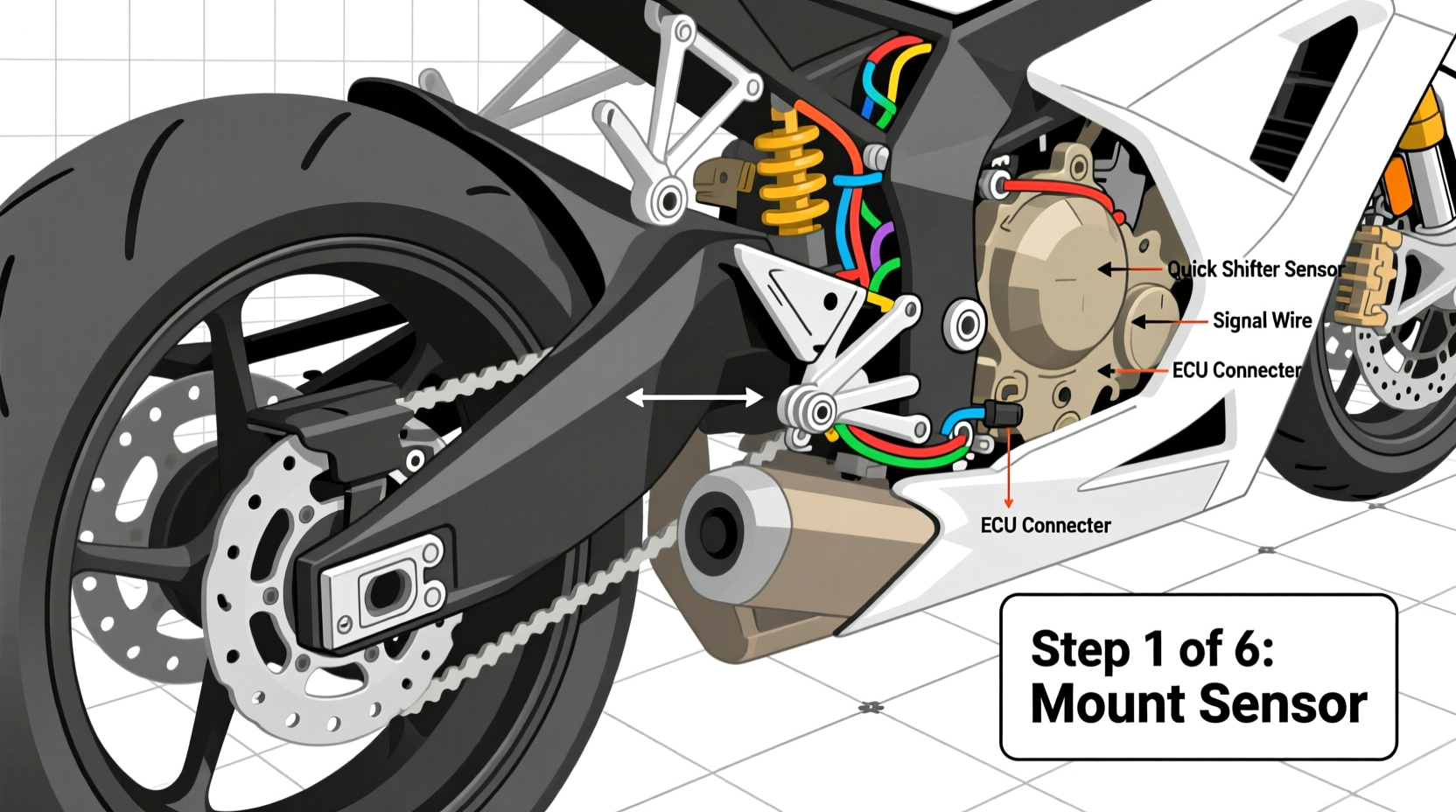
Step 2: Mount the Sensor
For microswitch kits: mount using supplied brackets so actuation occurs only during upward shift motion—not neutral or downshifts. Use thread-locker on mounting screws and verify switch plunger travel with a feeler gauge. For Hall-effect sensors: align the magnet precisely with the sensor face. Air gap must remain constant across full shift stroke—use a dial indicator if possible.
Step 3: Route Wires Safely
Route sensor wires away from exhaust headers (>50 mm clearance), moving suspension components, and sharp edges. Secure with high-temp nylon ties (rated ≥125°C) every 75 mm. Never splice into factory harnesses—use T-taps rated for automotive use (e.g., Posi-Tap) or solder + heat-shrink with adhesive-lined tubing.
Step 4: Connect to ECU or Interface Module
CAN-based systems connect to designated pins on the ECU’s diagnostic port or auxiliary connector. Consult your bike’s wiring diagram (available via Motorcycle-Service-Manuals.com). Common CAN high/low pinouts:
| Manufacturer | CAN High Pin | CAN Low Pin | Notes |
|---|---|---|---|
| Yamaha (2015+ R1) | Pin 12 (Gray/Red) | Pin 13 (Gray/Black) | Termination resistor required on non-daisy-chained setups |
| Kawasaki (ZX-10R 2016+) | Pin 10 (Green/White) | Pin 11 (Green/Black) | ECU must be in ‘Tuning Mode’ via dealer tool |
| Ducati (Panigale V4) | Pin 2 (Yellow/Blue) | Pin 3 (Yellow/Brown) | Requires Ducati Diagnostic Tool (DDT) for activation |
Step 5: Configure Cut Parameters
Using the manufacturer’s tuning software (e.g., Domino Tuning Suite, RapidBike EVO Configurator), set:
- Cut Duration: Start at 35–45 ms for 600cc–1000cc bikes; increase incrementally (5 ms steps) if shifts feel sluggish. Never exceed 65 ms—longer cuts risk lean spikes and catalytic converter damage.
- RPM Threshold: Set minimum activation RPM (e.g., 3,000 rpm) to prevent accidental engagement in traffic.
- Throttle Position Lockout: Enable >15% TPS lockout to avoid cutting during partial-throttle shifts.
Regional Considerations: US vs. EU vs. AU Compliance
Quick shifter legality varies significantly by jurisdiction—and affects both installation and usage:
- United States: No federal ban, but some states (e.g., California) prohibit modifications affecting emissions control. QS units that only interrupt ignition (not fuel) generally comply with CARB EO# exemptions. Verify your unit’s CARB Executive Order number before purchase.
- European Union: Must meet ECE R13-H (braking) and R10 (electromagnetic compatibility) standards. Since 2021, all QS-equipped bikes sold new in EU require type-approval documentation proving no impact on ABS or traction control logic. Aftermarket kits are exempt—but liability rests with the installer if a crash occurs.
- Australia: Road-registered bikes require QS to be listed on the vehicle’s ADR compliance plate. Queensland Transport explicitly bans QS use on public roads unless factory-fitted. Always check with your state RTA before finalizing installation.
Verification tip: Download your region’s latest Motor Vehicle Standards Bulletin (Australia), Code of Federal Regulations Title 40 (US), or EU Commission Regulation (EU) 2019/2144 (EU) and search for ‘gear shift intervention’ or ‘transient torque control’.
Common Misconceptions—Debunked
Misconception #1: “All quick shifters work the same way.”
False. Ignition-cut QS units (e.g., STM) preserve fuel delivery, minimizing post-shift lean conditions. Fuel-cut units (e.g., older Bazzaz) can cause decel popping and increased catalyst temperatures. Modern hybrid systems (e.g., Dynojet Quick Shifter Pro) cut both—precisely timed to maintain stoichiometric balance.
Misconception #2: “Plug-and-play means no tuning needed.”
Incorrect. Even OEM-integrated QS (e.g., Kawasaki BLIPPER) requires rider-specific calibration for optimal feel. Factory settings assume race-spec tires and track conditions—not street grip or worn sprockets.
Misconception #3: “Installing a QS voids my warranty.”
Not automatically. Under the Magnuson-Moss Warranty Act (US) and EU Directive 1999/44/EC, manufacturers cannot void warranties solely due to aftermarket parts—unless they prove the part caused the failure. Document all steps and retain OEM service records.
Troubleshooting: 5 Real-World Issues & Fixes
- Issue: QS activates only in 2nd–5th gears.
Solution: Check gear position sensor signal in live data. Many ECUs ignore QS input below 2nd gear for safety—reprogram cutoff table if supported. - Issue: Engine stutters after shift, then recovers.
Solution: Reduce cut duration by 5 ms and verify battery voltage stability during shift. Voltage sag >0.5 V indicates weak charging system. - Issue: QS works on stand but fails under load.
Solution: Inspect shift linkage for flex or binding. Install a rigid billet linkage arm—stock plastic or rubber-bushed arms deflect under torque, delaying sensor actuation. - Issue: Error code P1614 (CAN communication loss).
Solution: Measure CAN bus resistance between H/L lines at ECU connector—it must be 60 Ω ±5 Ω. Add 120 Ω termination resistor if only one node is on the bus. - Issue: No response despite correct wiring.
Solution: Use multimeter in continuity mode to trace sensor output to ECU pin. Open circuits often occur at crimp connectors—not solder joints.
Post-Installation Validation Protocol
Do not consider installation complete until you pass all three validation stages:
- Static Test: With ignition ON (engine OFF), manually actuate shift linkage while monitoring live data. Sensor signal must transition cleanly between 0 V and 5 V (or CAN message ID active/inactive) without bounce or delay.
- Dynamic Idle Test: At idle, perform 10 controlled upshifts. Zero misfires, no throttle blip anomalies, and consistent cut duration (±2 ms) in logged data.
- Road Test: Conduct 3 sessions: (a) city speeds (25–45 mph), (b) highway cruise (55–75 mph), (c) spirited riding (80–110 mph). Log GPS speed, RPM, TPS, and QS status. Review for latency >12 ms or inconsistent cut behavior.
Retain all logs for 30 days. They’re critical if warranty disputes arise—or if you later upgrade to a full engine management system.
Frequently Asked Questions
- Can I install a quick shifter on a carbureted motorcycle?
- No—carbureted engines lack the electronic fuel or ignition control required for precise transient torque management. Mechanical ‘slipper clutches’ or shift-assist levers are the only viable alternatives.
- Do I need a dyno tune after installing a quick shifter?
- Not for basic upshift functionality—but highly recommended if enabling downshift blipping or integrating with traction control. A dyno validates closed-loop AFR stability during cut events.
- Will a quick shifter work with a slipper clutch?
- Yes—and it’s strongly advised. A quality slipper clutch (e.g., STM, Rekluse) absorbs residual driveline shock, extending gearbox life when combined with aggressive QS cut timing.
- How long does professional quick shifter installation take?
- Experienced technicians average 3.2 hours (including diagnostics and validation). First-time DIYers should budget 6–8 hours—and plan for one rework cycle.
- Are wireless quick shifters reliable?
- Currently, no production-grade wireless QS meets ISO 11898-2 (automotive CAN) timing requirements. All certified systems use hardwired connections for sub-millisecond latency and EMI immunity.




 浙公网安备
33010002000092号
浙公网安备
33010002000092号 浙B2-20120091-4