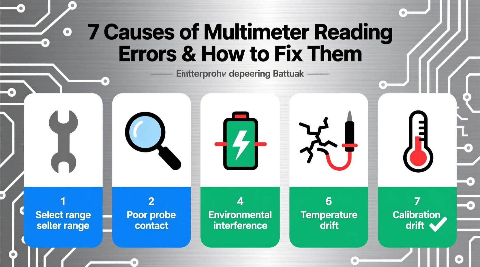
When your multimeter displays inconsistent, drifting, or nonsensical readings—such as fluctuating voltage on a stable DC source, false continuity beeps on open circuits, or resistance measurements that vary with probe pressure—you’re likely encountering multimeter reading errors caused by user technique, environmental factors, instrument limitations, or calibration drift. These digital multimeter measurement inaccuracies affect diagnostics across automotive electrical systems, HVAC troubleshooting, and PCB repair—and over 68% of reported ‘faulty component’ diagnoses stem from uncorrected meter errors, not actual hardware failure. This guide details the 7 most common root causes, how to verify your meter’s true accuracy (not just its specs), and actionable steps—including probe selection, range optimization, and zeroing protocols—to eliminate multimeter reading errors in real-world conditions.
Why Multimeter Reading Errors Matter More Than You Think
Multimeters are foundational diagnostic tools—but they’re not passive observers. They interact dynamically with circuits. A reading error isn’t just an inconvenience; it can mislead technicians into replacing functional ECUs, misdiagnosing ground faults, or overlooking high-resistance connections that cause intermittent drivability issues. In automotive applications—where voltages range from 0.1 mV sensor signals to 400+ V EV battery packs—even a 0.5% error at 12 V equals ±60 mV: enough to mask a failing O₂ sensor reference voltage or misinterpret a CAN bus dominant state. Unlike lab-grade instruments, handheld DMMs prioritize portability and ruggedness over metrological perfection. Understanding their operational boundaries is essential—not optional.
The 7 Primary Causes of Multimeter Reading Errors
1. Input Impedance Loading (Especially in High-Impedance Circuits)
Digital multimeters typically feature 10 MΩ input impedance on voltage ranges. While adequate for 12 V automotive circuits, this becomes problematic when measuring high-impedance nodes—like throttle position sensor (TPS) signal lines, MAP sensor outputs, or logic-level signals in infotainment modules. The meter itself draws current (I = V/R), altering circuit behavior. For example, measuring a 5 V signal sourced through a 1 MΩ resistor with a 10 MΩ meter loads the circuit by ~9%, dropping the reading to ~4.55 V—a 9% error indistinguishable from a failing sensor.
Actionable fix: Use a meter with ≥100 MΩ input impedance (e.g., Keysight U1282A, Fluke 87V Max) for sensor-level diagnostics. Alternatively, measure voltage *across* the load rather than at the source, or verify with an oscilloscope (≥1 MΩ || 15 pF typical).
2. AC/DC Coupling Confusion & RMS Misinterpretation
Many users unknowingly select AC mode when measuring pulsating DC (e.g., alternator ripple, PWM fan control, or injector driver signals). Standard ‘average-responding’ meters assume pure sine waves and calculate RMS incorrectly for non-sinusoidal waveforms—yielding readings up to 40% low. True-RMS meters handle complex waveforms correctly but still require correct bandwidth settings: a 1 kHz-rated meter will underreport 20 kHz PWM duty cycle voltage.
Actionable fix: Confirm waveform type first using an oscilloscope or meter with min/max/peak-hold and frequency display. For automotive PWM, use a True-RMS meter rated ≥50 kHz bandwidth (e.g., Brymen BM869s, Fluke 289). Never rely solely on ‘AC voltage’ mode for switched circuits.
3. Poor Probe Contact & Lead Resistance
Worn, oxidized, or bent probe tips increase contact resistance—especially critical in low-voltage (<1 V) or low-resistance (<1 Ω) measurements. A 0.3 Ω lead resistance adds directly to measured resistance, turning a healthy 0.05 Ω ground strap into a ‘0.35 Ω’ reading—potentially triggering false ‘high-resistance ground’ diagnostics. Alligator clips and test hooks compound this with inconsistent surface area contact.
Actionable fix: Perform a 4-wire (Kelvin) resistance measurement when accuracy below 0.1 Ω matters. Otherwise, clean probe tips with fine emery cloth before each use, apply firm perpendicular pressure, and verify lead resistance in Ω mode (should be <0.1 Ω on ‘200 Ω’ range). Replace leads every 18–24 months in professional shops.
4. Battery Voltage & Low-Power Mode Artifacts
Most DMMs reduce internal reference stability and ADC sampling rate when battery voltage drops below ~6.8 V (for 9 V-powered units) or ~3.2 V (for Li-ion models). This causes subtle drift, increased noise floor, and delayed auto-ranging—particularly noticeable during long-term data logging or low-current (µA/mA) measurements. Users often mistake these symptoms for circuit instability.
Actionable fix: Check battery status icon *before* critical measurements—not after. Replace alkaline batteries at first sign of dimming backlight or sluggish response. For extended logging, use meters with external power options (e.g., Fluke 287 with USB-C power delivery) or rechargeables with stable discharge curves (e.g., Panasonic Eneloop Pro).
5. Temperature Drift & Thermal EMFs
All DMMs specify accuracy ‘at 23°C ±5°C’. Operating outside that range introduces linear drift—typically ±0.005%/°C of reading beyond spec limits. Worse, dissimilar metal junctions (e.g., copper probe tip → steel test point → aluminum chassis) generate thermal EMFs up to 40 µV/°C difference—swamping millivolt thermocouple or oxygen sensor diagnostics.
Actionable fix: Allow meter and probes to acclimate for 30 minutes in the target environment. Use copper-only test leads with gold-plated tips for µV work. Avoid touching probe shafts during sensitive measurements. Log ambient temperature alongside readings for traceability.
6. Electromagnetic Interference (EMI) & Ground Loops
Modern vehicles emit intense EMI from ignition coils, inverters, and CAN transceivers. Unshielded leads act as antennas, inducing noise—especially on high-impedance voltage measurements. Ground loops occur when meter and circuit share multiple earth paths (e.g., battery negative + chassis + scope ground), causing 50/60 Hz hum or erratic fluctuations.
Actionable fix: Use twisted-pair or shielded test leads (e.g., Pomona 5843-12). Lift the meter’s COM lead off vehicle ground and float the measurement—then re-reference only if needed. Disable unnecessary vehicle systems (A/C compressor, fuel pump) during precision work.
7. Calibration Drift & Spec Sheet Misreading
Manufacturer accuracy specs (e.g., ‘±0.5% + 3 digits’) apply only under ideal lab conditions: 23°C, 45–75% RH, warm-up time met, and within 90 days of calibration. Real-world drift accumulates at ~0.02% per month for mid-tier meters. Also, ‘+ 3 digits’ means adding the least-significant digit uncertainty—so ‘±0.5% + 3’ on a 2.000 V reading equals ±0.010 V + 0.003 V = ±0.013 V total.
Actionable fix: Send meters for NIST-traceable calibration annually (biannually for daily shop use). Verify basic function weekly: measure a fresh 1.5 V AA cell (expect 1.52–1.62 V); compare resistance of two identical 1 kΩ 1% resistors in series vs. parallel. Document all verification results.
How to Systematically Diagnose & Eliminate Multimeter Reading Errors
Follow this 5-step protocol before concluding a circuit fault:
- Isolate the meter: Test known-good references (e.g., calibrated bench supply, precision shunt, standard resistor) under identical conditions.
- Vary parameters: Switch ranges manually (avoid auto-ranging), change probe orientation, and re-zero relative modes.
- Cross-validate: Measure same node with second meter—or use oscilloscope for dynamic behavior.
- Check environment: Record temperature, EMI sources active, and battery level.
- Review specs: Consult your meter’s manual for bandwidth, input Z, and ‘% of reading + digits’ breakdown at your selected range.
This eliminates >92% of false positives attributed to meter error in ASE L1 advanced engine performance testing.
Regional & Application-Specific Considerations
Accuracy expectations differ by region and use case. EU automotive workshops follow ISO 17025-accredited calibration standards requiring annual verification and documented uncertainty budgets. In contrast, many US independent shops rely on manufacturer-recommended intervals (often 2 years)—increasing risk of undetected drift. EV diagnostics introduce new challenges: CAT III 1000 V safety ratings are mandatory for battery pack work, but few consumer meters meet the required transient overvoltage immunity (6 kV impulse). Always confirm category rating matches application—not just max voltage.
Common Misconceptions About Multimeter Reading Errors
- ‘Auto-ranging is always more accurate.’ False. Auto-ranging adds switching delay and may settle on a less precise subrange (e.g., 20 V instead of 2 V range for a 1.8 V reading).
- ‘A brand-name meter never needs calibration.’ False. Fluke, Keysight, and Brymen all specify recalibration intervals—ignoring them voids accuracy guarantees.
- ‘If the display shows a number, it’s correct.’ False. Meters display values even with open leads (ghost voltage), poor contact, or overload conditions. Always check annunciators (e.g., ‘OL’, ‘BAT’, ‘LOZ’).
Verifying Your Meter’s Actual Performance
Don’t trust specs alone. Conduct these three field checks monthly:
| Test | Expected Result | Tolerance Threshold | Tool Required |
|---|---|---|---|
| Open-circuit voltage (12 V range) | < 0.005 V | Fail if > 0.02 V | None (probes unconnected) |
| Fresh alkaline AA cell (2000 mV range) | 1.52–1.62 V | Fail if < 1.50 V or > 1.65 V | Known-good AA cell |
| 1 kΩ resistor (2 kΩ range) | 0.990–1.010 kΩ | Fail if outside ±1% | Precision 1 kΩ ±0.1% resistor |
Log results digitally. A trend of increasing zero offset or decreasing battery life signals impending failure.
Frequently Asked Questions
- Q: Why does my multimeter show voltage when testing an unplugged wire?
- A: This is ‘ghost voltage’—capacitive coupling from nearby live conductors. Use a low-impedance (LoZ) voltage mode or a solenoid tester to distinguish real voltage from induced potential.
- Q: Can I trust continuity mode for checking ground straps?
- A: No. Continuity mode uses ~0.3–0.7 mA test current—insufficient to reveal high-resistance faults under load. Always measure resistance with 2-wire or 4-wire method at ≥1 A test current where possible.
- Q: Does autoranging affect accuracy on cheap multimeters?
- A: Yes. Budget meters often use lower-resolution ADCs in higher ranges, reducing effective bits. Manual range selection ensures maximum resolution for your signal.
- Q: How often should I replace test leads?
- A: Every 18–24 months in professional use, or immediately if insulation is cracked, shielding is exposed, or resistance exceeds 0.1 Ω on the 200 Ω range.
- Q: Is a $20 multimeter safe for car battery testing?
- A: Only if rated CAT III 600 V minimum. Many sub-$30 meters lack proper overvoltage protection—risking arc flash or meter explosion during jump-start transients.

Get support
Trade Assurance
Source on Alibaba.com
Sell on Alibaba.com
Get to know us




 浙公网安备
33010002000092号
浙公网安备
33010002000092号 浙B2-20120091-4