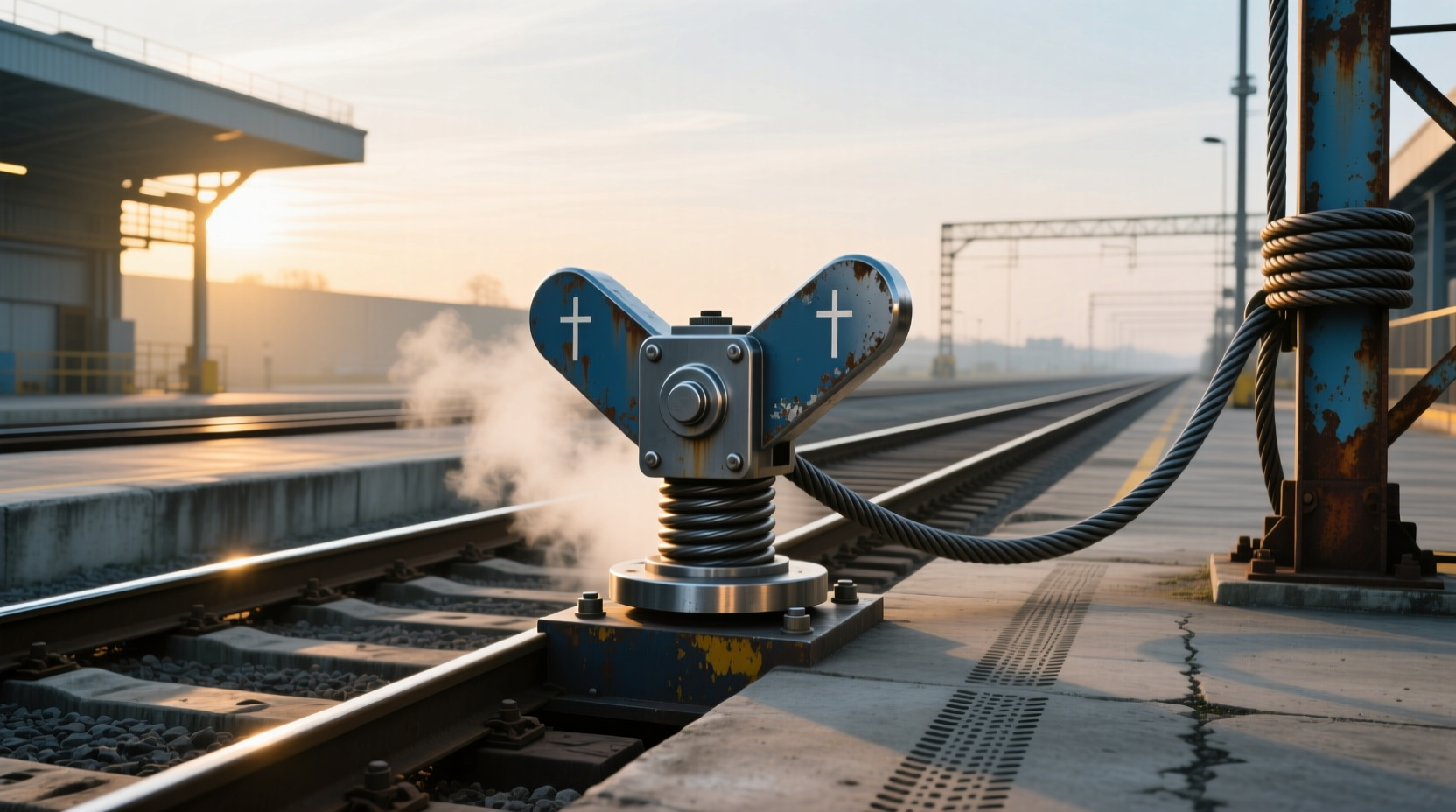
When a train reaches the end of a track, a critical safety device stands between controlled stopping and catastrophic overrun: the friction buffer stop. Among the most widely used systems in mainline and urban rail networks, friction buffer stops absorb kinetic energy through controlled mechanical resistance, preventing derailments and protecting infrastructure. Unlike solid bumper blocks or hydraulic variants, these systems are engineered to dissipate force gradually by sliding or shearing components under impact1. This makes them ideal for high-mass applications—such as freight terminals or commuter stations—where trains may fail to stop due to signal errors, brake failure, or human factors. In this guide, we’ll explore how friction buffer stops function, compare them with alternative designs, examine real-world performance data, and outline key selection criteria for engineers and maintenance teams.
Understanding the Role of Buffer Stops in Rail Safety ⚙️
Railway buffer stops, also known as bumping posts, bumper blocks, or stopblocks (in North America), serve one primary purpose: to prevent rolling stock from traveling beyond the physical end of a track segment2. While seemingly simple, their engineering is complex and mission-critical. A runaway train—even at low speed—carries immense momentum. For example, a passenger train weighing 400 tons moving at just 15 km/h possesses enough kinetic energy to cause structural collapse, endanger lives, and disrupt entire transit networks if not safely arrested.
There are three main categories of buffer stops:
- Fixed (rigid) buffer stops: Typically made of reinforced concrete or steel, these offer minimal give upon impact. They are cost-effective but can result in severe damage to both the train and the structure.
- Hydraulic buffer stops: Use fluid dynamics to absorb energy progressively. Effective for precise deceleration but require regular maintenance and can leak under extreme conditions. \li> Friction buffer stops: Rely on sliding surfaces, shear pins, or clamping mechanisms to convert motion into heat via friction. These balance durability, reliability, and energy dissipation without consumable fluids.
The choice among these depends on traffic type, vehicle mass, approach speed, space constraints, and environmental conditions. Friction-based systems have become increasingly popular in modern installations due to their passive operation, minimal upkeep, and predictable performance across varying climates.
How Friction Buffer Stops Work: The Mechanics Behind Energy Dissipation 🔧
At its core, a friction buffer stop operates on the principle of converting kinetic energy into thermal energy through controlled resistance. When a train impacts the buffer head, the force is transferred into an assembly designed to slide or deform along predefined paths. This movement generates friction between metal surfaces, effectively slowing the train over a short distance—typically 1 to 3 meters—depending on design specifications.
Key components include:
- Impact head: The front-facing element that makes initial contact with the train coupler or buffer beam.
- Sliding rails or beams: Guided tracks that allow horizontal displacement during engagement.
- Friction clamps or pads: High-strength materials (often composite or alloy-based) that create consistent resistance during sliding.
- Shear pins or sacrificial elements: Designed to break at specific load thresholds, ensuring predictable energy absorption and preventing excessive forces from transferring to the track bed.
- Anchoring system: Secures the unit to the rail foundation, often embedded in concrete or bolted to sleepers.
In operation, when a train strikes the buffer stop, the impact head pushes against the sliding mechanism. As it moves backward, friction pads engage, creating drag. Simultaneously, shear pins may fracture in sequence, allowing progressive release of energy. The cumulative effect is a controlled deceleration that minimizes peak g-forces on the train structure and passengers.
One notable example is the RAWIE mainline friction buffer stop, engineered for heavy freight and passenger service. According to manufacturer data, some models can withstand impacts up to 850 tons at speeds exceeding 10 km/h, making them suitable for terminal stations and shunting yards3.
Advantages and Limitations of Friction-Based Systems ✅
Like any engineering solution, friction buffer stops come with trade-offs. Understanding these helps operators make informed decisions based on operational needs.
| Feature | Friction Buffer Stop | Hydraulic Buffer Stop | Fixed Buffer Stop |
|---|---|---|---|
| Energy Absorption | Moderate to high (adjustable via design) | High (smooth, linear) | Very low (rigid) |
| Maintenance Needs | Low (inspect shear pins, friction surfaces) | High (fluid levels, seals, leaks) | Very low |
| Durability | High (no moving fluids) | Moderate (seals degrade) | High |
| Reset After Impact | Yes (replace pins, reset sliders) | Yes (refill fluid, inspect valves) | No (repair/replace structure) |
| Cost (Initial) | Moderate | High | Low |
| Environmental Resistance | Excellent (works in cold, wet, dusty) | Poor (fluid viscosity changes) | Excellent |
From this comparison, friction buffer stops emerge as a balanced option—offering significant energy absorption without the complexity of fluid systems. Their ability to operate reliably in harsh environments (e.g., arctic regions or coastal zones) gives them an edge over hydraulic alternatives.
However, they are not universally applicable. Because they rely on displacement, sufficient overrun distance must be available behind the stop. In space-constrained areas like underground stations or elevated platforms, even 2 meters of rearward travel may be impractical. Additionally, after activation, maintenance crews must inspect and replace shear pins or worn friction elements before reuse—a process that requires downtime and spare parts inventory.
Design Standards and Regulatory Compliance 📋
Friction buffer stops are subject to stringent international standards to ensure interoperability and safety. Key regulatory frameworks include:
- EN 13481-6: European standard for fixed track fastening systems, including buffer stop testing methods.
- UIC 719: International Union of Railways specification for buffer stop performance under various impact scenarios.
- AAR S-660: Association of American Railroads guideline for railroad bumping post strength and installation.
These standards define parameters such as maximum allowable deflection, energy absorption capacity, anchoring requirements, and dynamic test procedures. For instance, UIC 719 mandates full-scale crash tests using representative rolling stock to validate performance claims. Manufacturers must provide certification documentation showing compliance before deployment in public transit systems.
Operators should verify that any installed friction buffer stop meets local jurisdictional codes. In some countries, third-party inspection or periodic recertification is required—especially after an impact event. Failure to comply can lead to liability issues in case of accidents.
Installation Best Practices and Site Considerations 📍
Proper installation is crucial for effective performance. Even the most advanced friction buffer stop will underperform if improperly mounted or mismatched to site conditions.
Track Foundation Stability: The underlying ballast and subgrade must support both static loads and dynamic impact forces. Weak foundations can lead to settlement or tilting, reducing effectiveness.
Rail Continuity: Some friction buffer stops integrate directly with the running rails, while others use independent beams. Ensuring proper alignment prevents lateral displacement during impact.
Clearance Zone: A clear area behind the stop is essential to accommodate rearward movement. Obstructions such as signal cabinets, walls, or drainage structures must be set back appropriately.
Drainage and Corrosion Protection: In humid or saline environments, corrosion-resistant coatings and stainless steel components help extend service life. Proper drainage prevents water accumulation around anchor points, which could weaken concrete footings.
Manufacturers like Oleo Inc and voestalpine offer bespoke solutions tailored to site-specific geometries and loading profiles45. Customization options include angled approaches, dual-track configurations, and integration with derailment prevention systems.
Real-World Performance and Accident Mitigation ✈️
While rare, buffer stop overruns do occur. Notable incidents highlight the importance of proper design and maintenance:
- 2010 Hoboken Terminal Crash (USA): A NJ Transit train failed to stop and crashed through a hydraulic buffer stop, killing one person. Investigators found the system had exceeded its rated capacity due to excessive speed.
- 2018 Glasgow Queen Street (UK): A ScotRail train overran the platform but was safely stopped by a modern friction buffer stop with minimal damage.
Post-event analyses consistently show that well-maintained, correctly rated buffer stops significantly reduce injury risk and asset damage. However, no buffer stop can guarantee safety if the incoming kinetic energy exceeds design limits. Therefore, buffer stops are considered a last line of defense—not a substitute for active braking systems or signaling controls.
Common Misconceptions About Friction Buffer Stops ❓
Several myths persist about how these devices work:
- Myth: "A buffer stop can stop any train, regardless of speed."
Reality: All buffer stops have rated impact velocities (usually 5–15 km/h). Exceeding this compromises safety. - Myth: "Friction types wear out quickly and need frequent replacement."
Reality: With proper materials and maintenance intervals, many units last decades. - Myth: "They’re only for freight lines."
Reality: Modern friction stops are used in metro systems, light rail, and passenger terminals worldwide.
How to Choose the Right Friction Buffer Stop for Your Application 🛠️
Selecting the appropriate model involves evaluating several technical and operational factors:
- Maximum Train Mass: Determine the heaviest expected vehicle (including locomotives or multiple-unit trains).
- Approach Speed: Estimate worst-case scenario speed if brakes fail (often assumed at 10 km/h unless higher risks exist).
- Available Overrun Distance: Measure how far the buffer can move rearward without hitting obstacles.
- Environmental Conditions: Consider temperature extremes, moisture, dust, and exposure to chemicals.
- Maintenance Capabilities: Assess whether your team can perform inspections and replacements promptly.
Consulting with qualified railway engineers or certified suppliers ensures compatibility with existing infrastructure. Request detailed technical datasheets—including force-displacement curves and test reports—before procurement.
Maintenance and Inspection Protocols 🧰
To ensure long-term reliability, routine checks should include:
- Visual inspection for deformation, cracks, or misalignment.
- Verification of shear pin integrity (replace if deformed or missing).
- Checking friction pad thickness and surface condition.
- Confirming anchoring bolts are tight and corrosion-free.
- Testing sliding mechanism mobility (manually or via simulation).
Most manufacturers recommend quarterly visual inspections and annual functional assessments. After any impact event, immediate shutdown and comprehensive evaluation are mandatory before reactivation.
Future Trends in Buffer Stop Technology 🌐
Emerging innovations aim to enhance safety and monitoring capabilities:
- Smart sensors: Embedded strain gauges and accelerometers provide real-time impact data.
- Predictive analytics: AI models forecast wear patterns and suggest optimal maintenance windows.
- Modular designs: Allow easier upgrades and component swaps without full replacement.
- Composite materials: Lighter yet stronger alternatives to traditional steel alloys improve efficiency.
As automated train operations expand, buffer stops will increasingly integrate with onboard diagnostics and wayside control systems to form layered safety networks.
Frequently Asked Questions (FAQs)
Q: What is the difference between a friction buffer stop and a hydraulic one?
A: Friction buffer stops use mechanical resistance (sliding surfaces and shear pins) to absorb energy, while hydraulic types use fluid pressure. Friction models require less maintenance and perform better in extreme temperatures.
Q: Can a friction buffer stop be reused after an impact?
A: Yes, but only after inspection and replacement of sacrificial components like shear pins and worn friction pads. Full reset procedures must follow manufacturer guidelines.
Q: How much space does a friction buffer stop need behind it?
A: Typically 1 to 3 meters, depending on the model and expected impact energy. Always consult the technical specifications for exact clearance requirements.
Q: Are friction buffer stops suitable for high-speed lines?
A: No. They are designed for terminal ends where trains should already be stopped or moving slowly (<15 km/h). High-speed derailment protection uses different systems.
Q: Do all railways use the same type of buffer stop?
A: No. Selection depends on regional standards, traffic type, and infrastructure layout. Many countries use a mix of friction, hydraulic, and fixed types based on application.





 浙公网安备
33010002000092号
浙公网安备
33010002000092号 浙B2-20120091-4