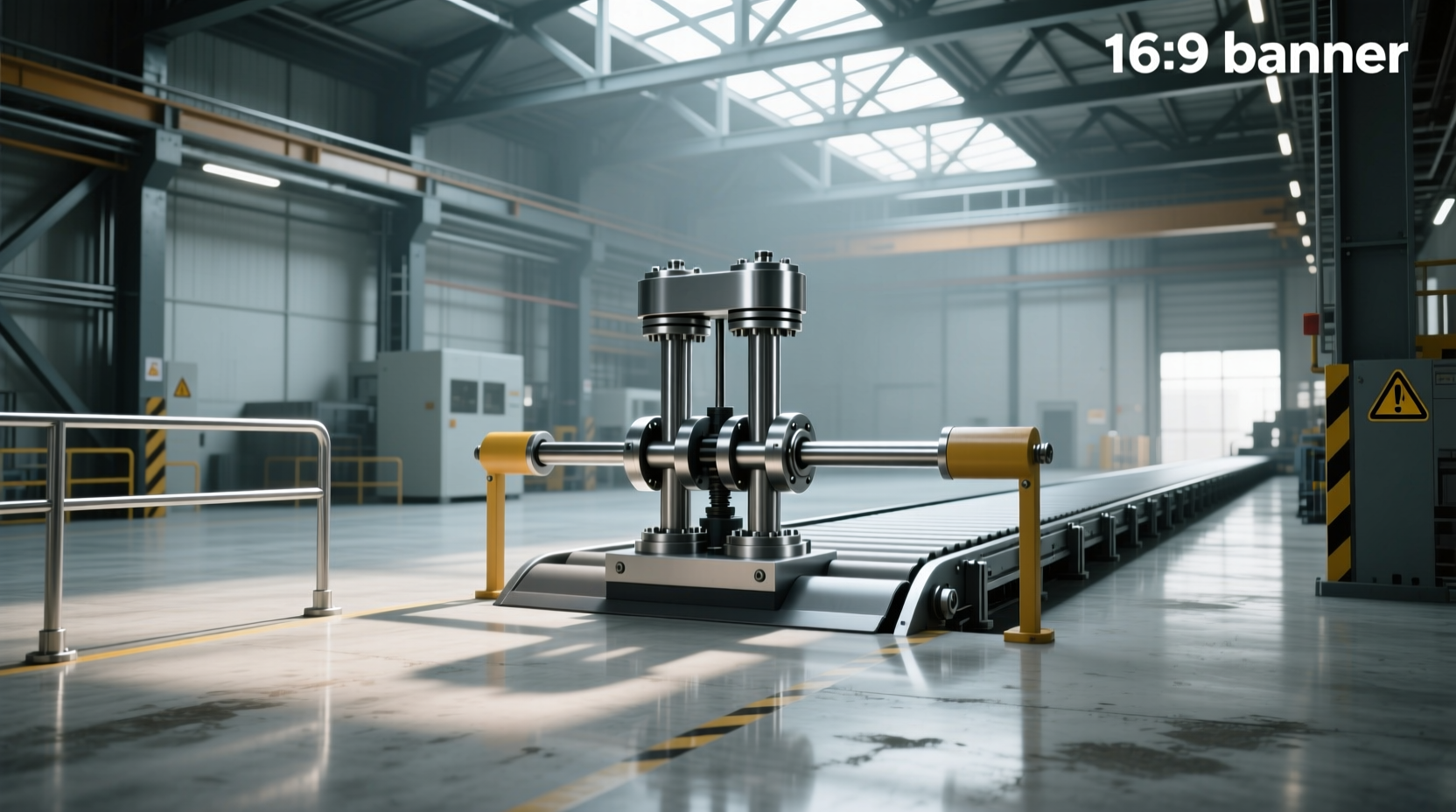
When a train fails to stop at the end of a track, the consequences can be catastrophic. That’s where hydraulic buffer stops come into play—engineered safety devices designed to absorb high-energy impacts and protect passengers, infrastructure, and rolling stock. Unlike traditional fixed or friction-based systems, hydraulic buffer stops use fluid dynamics to control deceleration, making them ideal for mainline railways, urban transit systems, and industrial terminals with higher-speed or heavier trains. This guide explains how they work, compares them to other types, outlines key selection criteria, and addresses common misconceptions about their performance and maintenance.
Understanding Buffer Stops in Rail Systems
A buffer stop (also known as a bumper block, bumping post, or stopblock) marks the physical end of a railway line. Its primary function is to prevent trains from overrunning tracks, which could lead to derailment, structural damage, or injury. While simple in concept, modern buffer stops are sophisticated mechanical systems engineered to handle specific kinetic energies based on train weight, speed, and operational environment.
There are several types of buffer stops used globally, including:
- Fixed buffer stops: Typically made of concrete or solid steel, these provide minimal energy absorption and are only suitable for very low-speed applications like yard shunting.
- Friction buffer stops: Use sliding mechanisms to dissipate energy through resistance. Effective for moderate speeds but require regular inspection and maintenance due to wear.
- Hydraulic buffer stops: Utilize oil-filled cylinders to convert kinetic energy into heat, offering controlled deceleration and high impact tolerance.
- Sliding-friction-hydraulic hybrids: Combine multiple technologies for maximum energy absorption in high-risk zones.
Among these, hydraulic models stand out for their ability to safely manage large masses moving at significant velocities—a critical factor in passenger rail networks and freight terminals 1.
How Hydraulic Buffer Stops Work: The Science Behind Impact Absorption
The effectiveness of a hydraulic buffer stop lies in its ability to manage force over time. Instead of stopping a train abruptly (which generates extreme g-forces), it extends the stopping distance by allowing controlled movement during impact.
Here’s how it works:
- Initial Contact: As the train touches the buffer head, push beams engage with hydraulic cylinders mounted behind the structure.
- Energy Conversion: Oil within the cylinders is forced through precision valves. This resistance converts the train’s kinetic energy into thermal energy (heat).
- Controlled Deceleration: The system regulates flow rate to maintain safe deceleration levels, typically below 0.5g to avoid passenger injury.
- Reset Capability: After an impact, many hydraulic units can be reset without replacement, reducing downtime and long-term costs.
This process allows a single unit to absorb anywhere from 1.5 MJ to over 8 MJ of energy, depending on design and configuration 2. For context, an 850-ton commuter train traveling at just 15 km/h carries approximately 7.3 MJ of kinetic energy—well within the capacity of a mid-range hydraulic buffer system.
Key Advantages of Hydraulic Over Other Types
While all buffer stops serve the same fundamental purpose, choosing the right type depends heavily on operational demands. Here's a comparison highlighting why hydraulic systems are preferred in high-performance environments:
| Feature | Fixed Buffer Stop | Friction Type | Hydraulic Type |
|---|---|---|---|
| Energy Absorption | Very Low | Moderate | High to Very High |
| Stopping Distance | Negligible (rigid) | 0.5–1.5 m | 1–3 m (adjustable) |
| Maintenance Frequency | Low | High (wear parts) | Moderate (seals, fluid checks) |
| Reset After Impact | Often requires full replacement | May need part replacements | Typically resettable |
| Ideal Use Case | Yards, sidings, model railways | Urban trams, light rail | Mainline stations, metro depots |
⚙️ Why this matters: In busy transit hubs, minimizing service disruption after an overrun incident is crucial. A hydraulic system that can be inspected and re-armed quickly offers superior operational continuity compared to rigid or friction-only alternatives.
Design and Installation Considerations
Selecting and installing a hydraulic buffer stop isn't a one-size-fits-all process. Engineers must evaluate several technical and environmental factors before deployment:
1. Train Parameters
The most critical inputs include:
- Maximum train mass (including locomotive + cars)
- Highest expected approach speed
- Buffer height and coupler alignment standards
These determine the total kinetic energy the system must absorb. Designers calculate using the formula: E = ½mv², where E is energy in joules, m is mass in kilograms, and v is velocity in meters per second.
2. Track Configuration
📍 Location influences stability requirements:
- End-of-line stations: Often have curved approaches, requiring asymmetric loading designs.
- Fall protection: If the track ends near a drop-off (e.g., elevated platforms), additional anchoring may be needed.
- Soil conditions: Soft ground may necessitate deeper foundations or pile support.
3. Integration with Signaling & Safety Systems
Modern installations often link buffer stops with signaling interlocks. For example, a train detection circuit upstream can trigger alarms or automatic braking if a vehicle approaches too fast. Some advanced systems even log impact data for post-event analysis ⚡.
4. Environmental Exposure
🔧 Hydraulic systems contain seals and fluids sensitive to temperature extremes. In regions with harsh winters or desert heat, manufacturers specify operating ranges (typically -30°C to +60°C). Units installed outdoors should have corrosion-resistant coatings and UV-protected components.
Common Misconceptions About Hydraulic Buffer Stops
Despite their proven reliability, several myths persist in both public and technical discussions:
Misconception 1: “They’re Only for High-Speed Trains”
❌ Not true. Even at low speeds, heavy freight trains carry substantial momentum. A 2000-ton freight car at 5 km/h has more energy than a passenger train at 10 km/h. Hydraulic buffers are valuable wherever mass or frequency increases risk.
Misconception 2: “They Eliminate the Need for Driver Vigilance”
❗ Incorrect. Buffer stops are last-resort safety measures. Relying on them instead of proper braking procedures creates unacceptable risks. They are not substitutes for ATP (Automatic Train Protection) or driver alertness.
Misconception 3: “All Hydraulic Models Are Interchangeable”
🚫 False. Different manufacturers use varying valve technologies, damping curves, and reset mechanisms. Compatibility with existing track geometry and maintenance protocols must be verified before procurement.
Maintenance and Inspection Best Practices
To ensure reliable performance, hydraulic buffer stops require scheduled upkeep. Recommended practices include:
- Monthly visual inspections: Check for oil leaks, bent push beams, loose bolts, or foundation cracks.
- Quarterly functional tests: Verify free movement and resistance consistency (where permitted by local regulations).
- Annual pressure and seal testing: Conducted by certified technicians using calibrated tools.
- Post-impact evaluation: Mandatory after any contact, regardless of severity. Includes review of deformation, fluid integrity, and structural soundness.
📋 Maintenance logs should be retained for audit purposes and integrated into broader asset management systems. Neglecting upkeep can void warranties and compromise safety certification 3.
Global Standards and Compliance Requirements
Hydraulic buffer stops must meet regional and international safety codes. Key standards include:
- EN 13481-6 (Europe): Specifies performance classes based on absorbed energy and test methods.
- AREMA Manual (North America): Provides guidance on placement, strength, and foundation design.
- UIC 724 (International Union of Railways): Covers general principles for terminal stops and collision protection.
🌐 Compliance ensures interoperability and legal defensibility in accident investigations. Always confirm that any purchased unit carries third-party certification (e.g., TÜV, SGS) relevant to your jurisdiction.
Cost Implications and Lifecycle Value
🛒 While hydraulic buffer stops have higher upfront costs than fixed models—ranging from $20,000 to $60,000 USD depending on capacity—their lifecycle value often justifies the investment:
- Reduced repair costs after minor overruns
- Lower downtime due to reset capability
- Potential insurance premium reductions
- Extended service life (typically 20+ years with care)
However, buyers should avoid selecting solely on price. Evaluate total cost of ownership, including installation complexity, spare parts availability, and technician training needs.
Applications Beyond Mainline Rail
🏭 Though primarily associated with railways, hydraulic buffer stops are also used in:
- Industrial plants: Protect loading docks and internal rail spurs handling raw materials.
- Port terminals: Secure container transfer lines exposed to tidal movements and crane operations.
- Mining operations: Installed on steep inclines where runaway cars pose serious hazards.
- Model railways (scaled versions): Enthusiasts modify small-scale hydraulic dampers for realism and durability.
Future Trends in Buffer Stop Technology
As rail systems become smarter and more automated, buffer stop technology is evolving accordingly:
- Smart sensors: Embedded accelerometers and strain gauges monitor real-time stress and predict fatigue.
- Remote diagnostics: IoT-enabled units send alerts when maintenance thresholds are reached.
- Regenerative systems: Experimental models capture some kinetic energy for reuse in station power grids.
- Modular designs: Allow incremental upgrades without full replacement.
⚡ These innovations aim to improve predictive maintenance, reduce human intervention, and enhance overall network resilience.
Conclusion: Making the Right Choice for Your Operation
Choosing the right buffer stop involves balancing safety, cost, and operational needs. For facilities dealing with medium to high-mass trains or those seeking minimal post-impact recovery time, hydraulic buffer stops offer unmatched performance and reliability. However, proper sizing, installation, and ongoing maintenance are essential to realize their full benefits.
Before specifying a system, consult with structural engineers and review historical overrun data. Engage suppliers who provide detailed technical documentation and support—not just hardware. And remember: no buffer stop replaces vigilant operation and robust signaling controls.
Frequently Asked Questions
❓ Can a hydraulic buffer stop stop a train at full speed?
No. Buffer stops are designed for low-speed overruns (typically under 15 km/h). They are not intended to stop trains traveling at line speed. Their role is to mitigate accidents caused by misjudged stops or brake failures near terminals.
❓ How much space does a hydraulic buffer stop need?
It depends on the model and energy rating. Most require between 1.5 and 3 meters of overrun zone to fully deploy. Always refer to manufacturer specifications and allow clearance for maintenance access.
❓ Are hydraulic buffer stops used in subways and metros?
Yes, extensively. Due to frequent service and tight schedules, metro systems often install hydraulic types for their reset capability and consistent performance after minor contacts.
❓ What happens after a train hits a hydraulic buffer stop?
After impact, the system compresses and absorbs energy. Technicians must inspect for damage, check fluid levels, and verify structural integrity before returning it to service. Some models automatically lock after activation until manually reset.
❓ Do hydraulic buffer stops require special training to maintain?
Yes. Servicing involves high-pressure systems and precision components. Only trained personnel should perform repairs or adjustments. Manufacturers typically offer certification programs for maintenance teams.





 浙公网安备
33010002000092号
浙公网安备
33010002000092号 浙B2-20120091-4