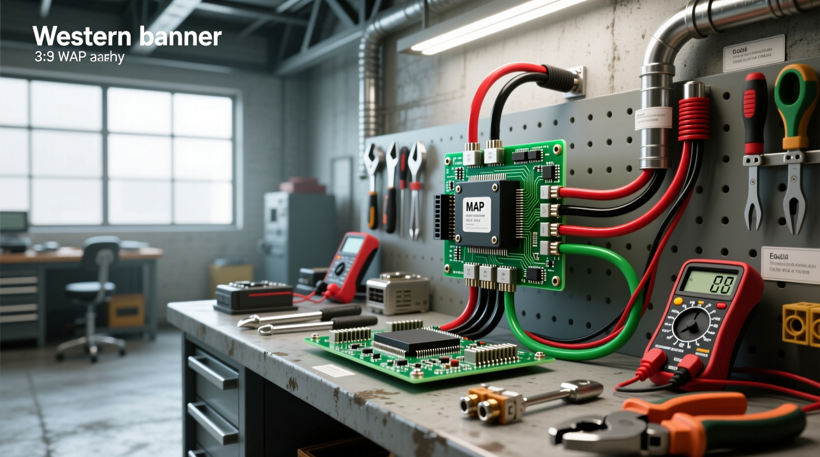
Understanding a 3 wire MAP sensor wiring diagram is essential for diagnosing engine performance issues, tuning your ECU, or installing an aftermarket sensor. The three wires—typically labeled as 5V reference, ground, and signal output—form the backbone of accurate manifold pressure readings that directly influence fuel delivery and ignition timing. Whether you're troubleshooting a P0107 code or upgrading to a 3-bar MAP sensor for forced induction, knowing how each wire connects and functions can prevent misfires, poor idle, or ECU faults.
What Is a MAP Sensor and Why Wiring Matters
A Manifold Absolute Pressure (MAP) sensor measures the air pressure inside the intake manifold and sends this data to the Engine Control Unit (ECU). This information helps the ECU calculate air density and determine optimal air-fuel ratio and spark timing. Unlike Mass Airflow (MAF) sensors, which measure incoming air volume, MAP sensors rely on pressure changes, making them especially useful in speed-density engine management systems.
Proper wiring of a 3-wire MAP sensor ensures stable voltage supply, clean signal return, and reliable grounding—all critical for accurate readings. Incorrect wiring can lead to incorrect fuel trims, stalling, hesitation, or even failure to start. In forced-induction applications like turbocharged or supercharged engines, using a higher-range MAP sensor (e.g., 3-bar instead of factory 2.5-bar) requires correct integration into the ECU harness.
Standard 3-Wire MAP Sensor Configuration
Most OEM and aftermarket 3-wire MAP sensors follow a universal configuration based on function, though wire colors may vary by manufacturer. Here’s the standard breakdown:
- Power/Reference Voltage (5V): Supplies regulated 5 volts from the ECU to power the sensor.
- Signal Output: Carries the variable voltage signal back to the ECU, proportional to manifold pressure.
- Ground (Sensor Ground): Provides a dedicated return path for the sensor circuit—not always chassis ground.
| Wire Function | Typical Color (GM) | Typical Color (Ford) | Typical Color (Generic) |
|---|---|---|---|
| 5V Reference | Orange | Light Green/Red | Red or Pink |
| Signal Output | Dark Blue | Gray/Light Blue | Green or Yellow |
| Ground | Black | Black/White | Black or Brown |
Note: Always verify with a multimeter or factory service manual before assuming wire colors. Some vehicles use shared grounds or combined MAP/IAT sensors with four wires, which should not be confused with a standard 3-wire setup.
Step-by-Step Wiring Process for 3-Wire MAP Sensors
Follow these steps when connecting or rewiring a 3-wire MAP sensor, whether during repair, replacement, or custom engine build:
- Identify the Connector Type: Most 3-wire MAP sensors use a weatherproof two- or three-pin connector. Check if it's keyed to prevent reverse insertion.
- Locate ECU Harness Wires: Trace back from the ECU connector or use a vehicle-specific wiring diagram to identify the correct pins for 5V ref, signal, and ground.
- Use a Multimeter to Confirm:
- With ignition ON (engine OFF), measure between ground and one wire—it should read ~5V (reference).
- Find the ground wire: continuity test to battery negative or known sensor ground.
- The remaining wire is the signal output.
- Solder and Insulate Connections: If splicing, use heat-shrink tubing or crimp connectors. Avoid electrical tape alone.
- Route Wires Safely: Keep away from exhaust manifolds, moving parts, and high-voltage ignition wires to prevent interference.
- Test Before Startup: Verify no shorts, proper voltages, and secure connections.
Common Wiring Mistakes and How to Avoid Them
Even experienced mechanics can make errors when dealing with MAP sensor wiring diagrams. Here are frequent pitfalls:
- Mixing Up Signal and Reference Wires: Connecting 5V to the signal line can damage the ECU input circuitry.
- Using Chassis Ground Instead of Sensor Ground: Shared or corroded grounds introduce noise and inaccurate readings.
- Ignoring Voltage Drop Over Long Runs: In custom harnesses, undersized wire gauge (>18 AWG) can reduce 5V supply under load.
- Incorrect Pigtail Use: Aftermarket pigtails must match the sensor’s connector type and pin layout.
To avoid these issues, always double-check with a digital multimeter and refer to OEM schematics where possible.
Differences Between 3-Wire and 4-Wire MAP Sensors
While both types serve similar purposes, understanding the distinction prevents compatibility issues:
| Feature | 3-Wire MAP Sensor | 4-Wire MAP Sensor |
|---|---|---|
| Wires | 5V, Signal, Ground | 5V, Signal, Ground, IAT or Boost Enable |
| Function | Pressure only | Pressure + Intake Air Temp or dual range |
| Common Applications | Naturally aspirated engines | Turbocharged engines (e.g., GM LS variants) |
| ECU Requirements | Speed-density system | May require calibration for IAT input |
A 4-wire version often integrates an Intake Air Temperature (IAT) sensor, combining two inputs into one housing. Do not attempt to connect a 4-wire sensor to a 3-wire harness without modifying the ECU map or adding pull-up resistors.
Testing a 3-Wire MAP Sensor with a Multimeter
After wiring, perform basic tests to confirm operation:
- Check 5V Reference: Turn ignition ON, measure voltage between 5V wire and ground. Should read 4.8–5.2V.
- Verify Ground Continuity: Use ohmmeter mode; resistance should be less than 0.5Ω.
- Measure Signal Output at Idle: Typically 0.8–1.3V depending on altitude and engine load.
- Apply Vacuum and Monitor Change: Using a hand pump, apply increasing vacuum (up to 20 inHg); signal voltage should decrease smoothly.
- Full-Scale Test (if applicable): For 3-bar sensors, pressurize slightly above atmospheric (e.g., 7 psi) to see if signal approaches 4.5–5.0V.
If readings are erratic, stuck, or out of expected range, inspect wiring, connector condition, or replace the sensor.
Upgrading to a 3-Bar MAP Sensor: What You Need to Know
For performance builds involving forced induction, upgrading from a stock 2.5-bar MAP sensor to a 3-bar unit allows accurate measurement beyond atmospheric pressure. However, this upgrade isn’t plug-and-play in all cases:
- Compatibility: Ensure your ECU supports 3-bar scaling. Factory ECUs may need reflashing.
- Wiring: Most 3-bar sensors still use 3-wire configurations but output higher voltage at boost levels.
- Calibration: Tuning software must recognize the new transfer function (voltage vs. pressure curve).
- Mounting: Install close to the intake manifold with minimal hose length to reduce lag.
Popular platforms like GM LS engines commonly support 3-bar upgrades with simple harness swaps and tuning adjustments.
Finding Reliable Wiring Diagrams by Vehicle
Vehicle-specific diagrams are crucial because wire colors and pin positions differ across brands. Here’s how to find trustworthy sources:
- OEM Service Manuals: Brands like GM, Ford, and Toyota publish detailed wiring schematics.
- University Research Labs: Institutions like Clemson Vehicular Electronics Laboratory provide educational resources on sensor circuits1.
- Forums and Technical Communities: Sites like TDIClub Forums or r/MechanicAdvice offer real-world insights from users who’ve completed similar projects.
- ECU Manufacturer Guides: Haltech, Holley, and MoTeC publish wiring specifications for standalone systems.
When searching online, include your vehicle make, model, year, and engine code (e.g., “LS1 3-wire MAP sensor wiring diagram”) to narrow results.
Troubleshooting Common MAP Sensor Errors
Several diagnostic trouble codes relate directly to wiring problems:
- P0107 – MAP Sensor Circuit Low Input: Often caused by open circuit in signal wire or short to ground.
- P0108 – MAP Sensor Circuit High Input: Could indicate short to power or faulty sensor.
- P0105 – MAP Sensor Circuit Malfunction: General fault covering wiring, connection, or internal sensor failure.
Before replacing the sensor, check:
- Connector for bent pins or moisture
- Wires for chafing or cuts near sharp edges
- Voltage supply stability under load
- Presence of vacuum leaks affecting actual pressure
Can You Run an Engine Without a MAP Sensor?
In most modern fuel-injected engines, removing or disconnecting the MAP sensor will trigger limp mode or prevent startup altogether. The ECU relies on manifold pressure data to calculate fuel delivery in speed-density systems. While some older engines used MAF-only setups, many cannot operate safely without a functioning MAP sensor. Bypassing it without proper substitution (like a calibrated potentiometer) is not recommended.
Best Practices for Installing MAP Sensor Wiring
To ensure long-term reliability and accuracy:
- Use OEM-Grade Connectors: Weather-sealed plugs prevent corrosion.
- Keep Wires Away from Noise Sources: Route away from alternators, coils, and injectors.
- Secure with Zip Ties: Prevent vibration fatigue.
- Label Wires: Especially important in custom harnesses.
- Double-Check Polarity: Reversed connections can destroy sensors or ECU inputs.
Conclusion: Mastering 3-Wire MAP Sensor Integration
A clear understanding of the 3 wire MAP sensor wiring diagram empowers DIYers and technicians to install, troubleshoot, and optimize engine management systems confidently. By identifying each wire’s role, verifying connections with proper tools, and referencing accurate schematics, you can avoid common pitfalls that lead to drivability issues. Whether restoring a classic, tuning a performance build, or repairing a daily driver, precise attention to MAP sensor wiring pays dividends in engine responsiveness, efficiency, and longevity.
Frequently Asked Questions
- What are the three wires on a MAP sensor? They are the 5-volt reference (power), signal output (data to ECU), and ground (circuit return).
- Can you run without a MAP sensor? Most modern engines cannot run properly without a MAP sensor; the ECU lacks critical load data needed for fuel calculation.
- How can the MAP sensor be connected to the intake manifold? Via a small-diameter vacuum hose routed from a port on the intake manifold to the sensor’s barbed fitting.
- How many electrical terminals does a MAP sensor have? A standard 3-wire MAP sensor has three terminals—one for power, one for signal, and one for ground.
- Are MAP sensor wire colors standardized? No, colors vary by manufacturer. Always verify with a multimeter or service manual rather than relying solely on color.





 浙公网安备
33010002000092号
浙公网安备
33010002000092号 浙B2-20120091-4