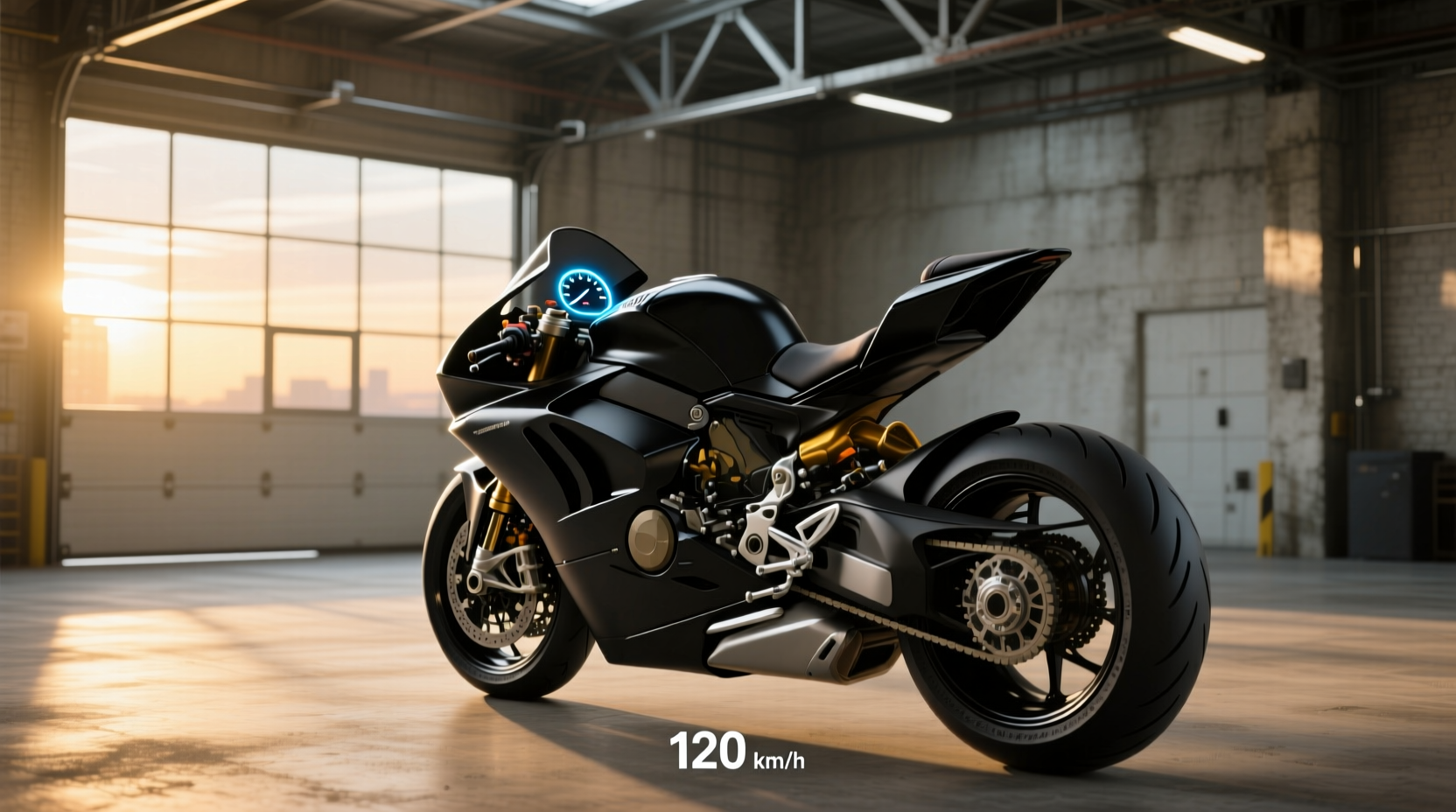
When upgrading or replacing your motorcycle’s stock instrumentation, a universal digital speedometer for motorcycle offers flexibility, modern features, and broad compatibility across custom builds and older models. Unlike OEM gauges, universal units are designed to work with various engine types, voltage systems (typically 9–16V), and mounting configurations, making them ideal for café racers, choppers, scramblers, and DIY restoration projects. However, choosing the right model requires understanding key specs like sensor type, display functionality, calibration methods, and wiring requirements—common pain points users face when searching for reliable aftermarket solutions.
What Is a Universal Motorcycle Speedometer?
A universal speedometer is an aftermarket instrument cluster designed to fit multiple motorcycle makes and models without requiring brand-specific integration. These units typically support both KM/H and MPH readings, include integrated odometers, trip meters, backlighting, and often combine tachometer (RPM) functions in one compact display. Unlike factory-installed analog dials, universal digital versions use electronic sensors—either magnetic reed switches or Hall-effect sensors—to detect wheel or transmission rotation and calculate speed accurately.
They are commonly used in three scenarios: restoring vintage bikes with non-functional original gauges, building custom motorcycles from scratch, or upgrading outdated instrumentation on older models. Because they don’t rely on proprietary communication protocols (like CAN bus systems found in newer bikes), these devices offer plug-and-play simplicity—but only if matched correctly to your bike’s electrical system and physical layout.
Key Features of Universal Digital Speedometers
To make an informed decision, it's essential to evaluate the core components and capabilities that define performance and usability:
Display Type: LCD vs LED vs TFT
LCD displays are the most common in budget-friendly universal speedometers. They provide clear readouts under normal lighting but may require backlighting for nighttime visibility. Many models feature blue, green, or white backlights with adjustable brightness.1
LED-based units offer higher contrast and better daylight readability. Some integrate segmented digits similar to vintage digital watches, while others use dot-matrix layouts for additional data fields such as gear position or coolant temperature.
TFT screens, though less common due to cost, deliver full-color graphics, customizable themes, and multi-function dash interfaces. These are typically seen in high-end universal clusters aimed at tech-savvy riders who want smartphone connectivity or GPS integration.
Speed Sensing Technology
Most universal speedometers use one of two sensing methods:
- Magnetic Sensor (Reed Switch): A small magnet mounted on a rotating part (e.g., front axle or drive sprocket) passes by a stationary sensor, generating pulses proportional to wheel speed. Simple and durable, but prone to interference from nearby metal objects.
- Electronic (Hall-Effect) Sensor: More reliable and accurate than reed switches, this solid-state sensor detects changes in magnetic fields without physical contact, reducing wear over time.
The number of pulses per mile/kilometer must be calibrated during installation—a step many first-time users overlook, leading to inaccurate readings.
Integrated Functions Beyond Speed
Modern universal units often go beyond basic speed indication. Common added features include:
- Odometer and dual trip meters
- Digital tachometer (RPM gauge)
- Voltmeter (battery health monitoring)
- Hour meter (engine runtime tracking)
- Backlight control (automatic or manual)
- Gear indicator (requires connection to neutral switch and RPM signal)
- Fuel level input (when connected to sender unit)
While more functions increase utility, they also complicate wiring and setup. Riders should assess which features are actually needed versus those that add unnecessary complexity.
Compatibility Considerations Before Buying
Not all universal speedometers truly work universally. Several technical factors determine whether a given model will function properly on your motorcycle:
Voltage Requirements
Most universal gauges operate within a 9–16V DC range, compatible with standard 12V motorcycle electrical systems. However, some older bikes with 6V systems or modified EV-powered builds may require voltage regulators or step-down converters. Always verify input voltage tolerance before purchase.
Pulse Signal Calibration
Each speedometer expects a specific number of sensor pulses per kilometer or mile. Mismatched calibration leads to incorrect speed readings—sometimes off by 20% or more. For example, a unit expecting 4,000 pulses/km will misread speed if your sensor generates only 2,000.
Many digital units allow manual calibration through menu settings. This usually involves riding a known distance (e.g., between two mile markers) and entering the actual distance traveled into the device. Instructions vary by manufacturer, so consult the manual carefully.
Engine Cylinder Count Support
If using the built-in tachometer, ensure the speedometer supports your engine’s cylinder configuration (single, twin, inline-four, etc.). The tach signal must match ignition firing patterns; otherwise, RPM readings will be erratic or doubled/halved.
Mounting Options and Size Constraints
Universal speedometers come in various sizes, typically ranging from 50mm to 80mm in diameter. Measure available space on your handlebars, headlight nacelle, or dashboard before selecting a model. Some units include rubber gaskets and metal brackets for vibration resistance, crucial for long-term durability.
| Feature | Typical Range / Options | User Impact |
|---|---|---|
| Display Type | LCD, LED, TFT | Affects visibility, power draw, and aesthetics |
| Voltage Input | 9–16V DC | Must match bike’s charging system |
| Speed Sensor Type | Reed switch, Hall-effect | Determines accuracy and installation method |
| Calibration Method | Manual ride-test or preset P/K ratio | Critical for accurate speed reading |
| Additional Gauges | Tach, voltmeter, fuel, temp | Increases wiring complexity |
Installation & Wiring Basics
Proper installation ensures reliability and prevents damage to the speedometer or bike’s electrical system. While exact steps depend on the model, general principles apply:
Wiring Connections Explained
A typical universal digital speedometer has 4–6 wires:
- Red: +12V power (connects to switched ignition source)
- Black: Ground (attach to clean frame point or battery negative)
- White or Yellow: Speed sensor input (connects to pickup sensor wire)
- Green: Tachometer signal (connects to spark plug coil or ECU tach output)
- Blue: Backlight control (optional, connects to running lights)
- Orange: Illumination or accessory output (powers other gauges)
Always refer to the included wiring diagram. Incorrect connections can fry internal circuitry.
Sensor Placement Tips
For optimal signal detection:
- Mount the sensor close (within 2–3mm) of the rotating magnet.
- Avoid placing near large ferrous metals that could distort the magnetic field.
- Secure wiring with zip ties to prevent snagging or abrasion.
- Use heat-shrink tubing on splices for moisture protection.
Calibrating Your Speedometer
After installation, calibration is mandatory. Here’s a standard procedure:
- Start the engine and confirm the display powers on.
- Enter calibration mode (usually by holding a button during startup).
- Ride exactly 1.0 mile or 1.0 kilometer on a flat road at moderate speed.
- Stop and confirm the distance traveled matches the actual route.
- Exit calibration mode—the device stores the new pulse-to-distance ratio.
Repeat if initial results show significant deviation (>5%).
Common Pitfalls and How to Avoid Them
Despite their plug-and-play claims, many users encounter issues post-installation. Awareness helps prevent frustration:
Inaccurate Speed Readings
Cause: Improper calibration, wrong tire size, or mismatched sensor pulse count.Solution: Recalibrate using precise distance markers. If tire diameter differs significantly from stock, adjust expected pulses accordingly.
Flickering Display or Random Resets
Cause: Poor grounding, voltage spikes, or insufficient power supply.Solution: Ensure ground wire connects directly to the battery negative terminal or a clean, unpainted chassis point. Use a multimeter to check for stable 12V under load.
Tachometer Not Working or Showing Double RPM
Cause: Incorrect tach signal source or incompatible ignition system (e.g., wasted spark).Solution: Connect to a single-cylinder coil lead rather than the ECU output unless specified. Adjust tach scaling in settings if available.
No Speed Signal Despite Correct Wiring
Cause: Faulty sensor, broken magnet, or incorrect gap between sensor and rotor.Solution: Test sensor continuity with a multimeter. Replace if open circuit. Realign magnet and sensor for consistent triggering.
GPS-Based vs Sensor-Based Universal Speedometers
An emerging alternative is the GPS-enabled universal speedometer, which calculates speed via satellite signals instead of mechanical sensors. These eliminate the need for wheel-mounted hardware and automatically adapt to tire size changes.
Advantages:
- No sensor installation required
- Self-calibrating across different vehicles
- Often includes additional navigation features
Disadvantages:
- Signal loss in tunnels or urban canyons
- Higher latency in acceleration/deceleration response
- Greater power consumption
- Typically more expensive
For riders prioritizing simplicity and real-time responsiveness, traditional sensor-based models remain preferable. GPS units suit touring applications where occasional dropouts are acceptable.
Regional Differences and Legal Compliance
In some countries, including the UK and EU nations, modifying instrumentation may affect vehicle inspection (MOT) compliance. While adding a secondary speedometer is generally permitted, replacing the primary OEM unit could raise regulatory concerns, especially if the replacement lacks official certification.
Always verify local regulations before removing or disabling factory-installed gauges. In many cases, retaining the stock speedometer—even non-functional—is advisable for passing inspections.
When NOT to Buy a Universal Speedometer
Despite their versatility, universal units aren’t suitable for every situation:
- Modern CAN Bus Motorcycles: Bikes manufactured after 2015 often rely on digital networks to transmit speed data. Adding a standalone analog-style gauge won't interface seamlessly without a CAN decoder module.
- High-Vibration Environments: Cheaply made units may suffer LCD delamination or solder joint cracks over time. Look for shock-resistant designs if riding off-road frequently.
- Need for OEM Integration: If you want turn-signal indicators, cruise control status, or gear-position display synced with the ECU, a universal gauge likely won’t support these without extensive modification.
Final Selection Checklist
Before purchasing a universal digital speedometer for motorcycle use, ask yourself:
- Does it support my bike’s voltage system?
- Can I calibrate the speed reading manually?
- Is the display readable in direct sunlight?
- Are mounting dimensions compatible with my build?
- Does it offer necessary functions without excess clutter?
- Does the tachometer support my engine type?
- Is there clear documentation for wiring and setup?
Selecting based on verified needs—not just price or appearance—ensures long-term satisfaction and safe operation.
Frequently Asked Questions (FAQs)
- Can I install a universal speedometer on any motorcycle?
- Yes, provided the voltage matches and you can mount the sensor properly. However, bikes with CAN bus systems may need additional modules for full compatibility.
- How do I calibrate a universal motorcycle speedometer?
- Ride a known distance (1 mile or 1 km), then enter that value into the calibration menu. The device adjusts its internal pulse counting to match real-world travel.
- Do universal speedometers work with LED headlights and modern electrical systems?
- Most do, as long as the system provides stable 12V DC power. Avoid tapping into circuits with PWM (pulse-width modulation) dimming unless specified.
- Why is my digital speedometer showing incorrect speed?
- Common causes include improper calibration, worn tires, incorrect sensor alignment, or mismatched pulse settings. Recalibrate first, then inspect hardware.
- Are GPS speedometers better than sensor-based ones?
- GPS models avoid mechanical sensors but can lose signal in obstructed areas. Sensor-based units respond faster and are more reliable for performance riding.




 浙公网安备
33010002000092号
浙公网安备
33010002000092号 浙B2-20120091-4