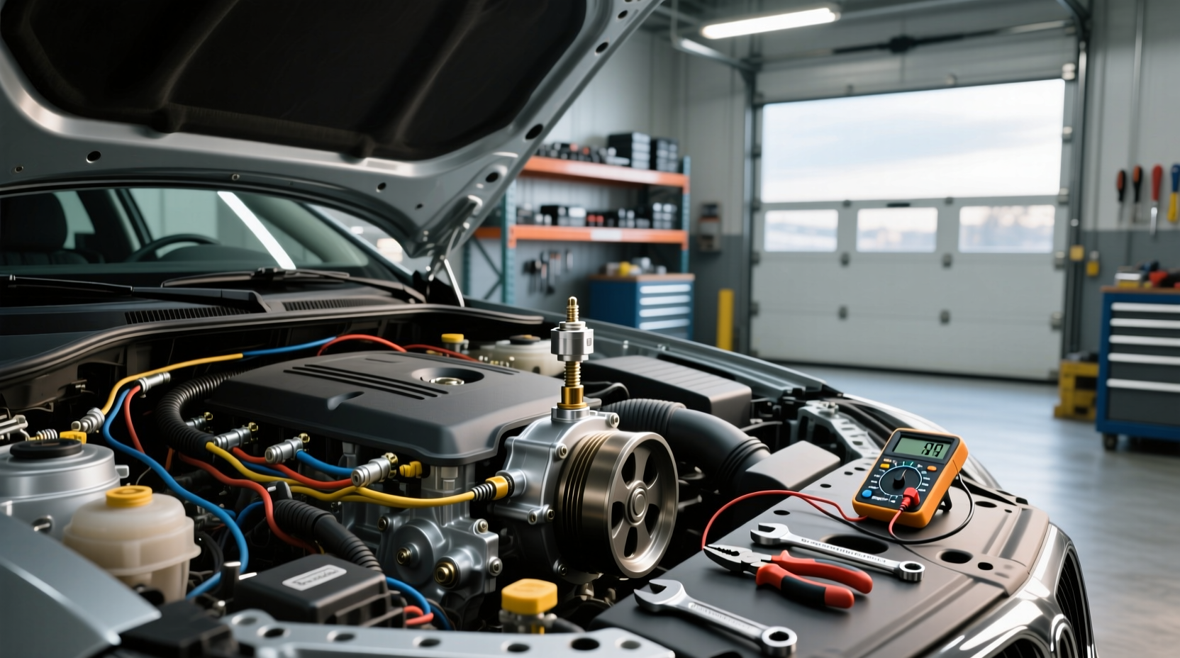
If you're searching for the engine RPM sensor location, you're likely troubleshooting a no-start condition, erratic tachometer readings, or diagnostic trouble codes related to engine speed. The engine RPM sensor—also known as the engine speed sensor, crankshaft position sensor (CKP), or magnetic pickup—is critical for monitoring rotational speed and enabling proper fuel injection and ignition timing. Its location varies significantly depending on engine type, manufacturer, and model year. In most vehicles, it's found near the crankshaft, flywheel, harmonic balancer, or transmission bellhousing. This guide will walk you through exact placement across common engine platforms, help you identify the sensor visually, explain failure symptoms, and provide step-by-step inspection and testing methods.
What Is an Engine RPM Sensor and Why Does Location Matter?
The engine RPM sensor measures how fast the crankshaft or camshaft is rotating and sends this data to the engine control unit (ECU). This signal is essential for calculating ignition timing in gasoline engines and fuel injection timing in both gasoline and diesel engines 1. Without an accurate RPM signal, the ECU cannot synchronize fuel delivery or spark, leading to stalling, hard starts, or complete engine shutdown.
Knowing the exact engine RPM sensor location matters because:
- 📍 It helps avoid unnecessary disassembly when diagnosing starting issues
- 🔧 Misdiagnosis is common if technicians assume a universal position
- ⚙️ Some sensors require precise air gap adjustment during installation
- 🛒 Replacement parts are often specific to engine family and mounting style
While modern OBD2 scanners can detect RPM sensor faults, physically locating and inspecting the sensor remains crucial—especially in older diesel engines or marine applications where communication protocols may be limited.
Common Names and Types of RPM Sensors
Before identifying location, understand that the RPM sensor goes by several names depending on context:
- Crankshaft Position Sensor (CKP): Most common term in passenger vehicles
- Engine Speed Sensor (ESS): Used in service manuals and diagnostics
- Magnetic Pickup Sensor: Common in diesel generators and industrial engines
- Hall Effect Sensor: Digital output type used in newer engines
- Variable Reluctance Sensor: Analog AC-output sensor, often found in older models
Sensor types affect not only function but also placement. For example:
| Sensor Type | Signal Output | Typical Location | Common Applications |
|---|---|---|---|
| Variable Reluctance | Analog AC voltage | Near crankshaft pulley or flywheel | Pre-2000 gasoline engines, many diesels |
| Hall Effect | Digital square wave | Timing cover, cylinder block side | Modern EFI systems, some diesel pumps |
| Magnetic Pickup | AC pulse signal | Flywheel housing, distributor base | Generators, marine diesels, Cummins |
Where Is the Engine RPM Sensor Located? By Engine Type
📍 Gasoline Engines (Front-Wheel Drive Vehicles)
In most front-wheel drive cars and SUVs with transverse-mounted engines (e.g., Honda, Toyota, Ford), the crankshaft position sensor is typically located:
- Near the crankshaft pulley (harmonic balancer) at the front of the engine
- Behind the lower timing cover, just above the oil pan
- Sometimes integrated into the transmission bellhousing
🔍 Example: 2010 Honda Accord 2.4L
The CKP sensor is mounted behind the crankshaft pulley, accessible from underneath the vehicle. You’ll need to remove the splash shield and sometimes the serpentine belt to reach it.
📍 Diesel Engines (Including Trucks and Generators)
Diesel engines often use a magnetic pickup sensor that reads teeth on the flywheel or flexplate. These are usually located:
- On the transmission bellhousing, pointing toward the flywheel
- Near the starter motor mount
- At the rear of the engine block in inline configurations
🔧 Example: 6.7L Cummins (2007–2018)
The engine RPM sensor (part number 3034572) is mounted on the left side of the engine, near the flywheel housing. It’s a dual-output magnetic sensor used for both tachometer signaling and ECM input.
🚢 Marine Diesel Applications
On Yanmar or Kubota-based marine engines, the RPM sensor is often threaded into the flywheel housing and requires sealing against moisture. Some aftermarket kits use hall effect sensors mounted near the alternator rotor.
📍 Rear-Wheel Drive and V8 Engines
In RWD vehicles (e.g., Chevrolet trucks, Mustangs), the sensor location varies:
- Some LS-series GM engines have the CKP near the rear main seal, close to the transmission
- Ford Modular V8s (4.6L, 5.4L) often place it near the crankshaft damper at the front
- Dodge HEMI engines use a front-mounted sensor behind the timing cover
📌 Tip: Always check both ends of the crankshaft. If you don’t find the sensor at the front, look near the bellhousing.
📍 Small Engines and Generators
Portable diesel generators (e.g., Perkins, Kubota) commonly use a magnetic speed pickup screwed into the governor housing or flywheel shroud. These generate an AC voltage proportional to engine speed and connect directly to analog tachometers.
🛠️ Testing Tip: Use a multimeter in AC mode. With the engine running, you should see increasing AC voltage as RPM rises (typically 0.5V to 5V AC).
How to Identify the RPM Sensor Visually
The engine RPM sensor is usually a small cylindrical or rectangular component with a single electrical connector and a two-wire harness. Key identifiers include:
- 📏 Size: About 1 to 2 inches long
- 🔌 Wire: Two wires (signal and ground), sometimes shielded
- 🔩 Mount: Threaded body with a hex base, secured with one bolt
- 🧲 Tip: May have a magnetic end or built-in magnet
❌ Don’t confuse it with:
- Camshaft position sensor (often nearby but smaller)
- Oil pressure sensor (usually on the engine block, different connector)
- Transmission speed sensor (located on the transmission body)
Symptoms of a Failing RPM Sensor
A faulty engine RPM sensor disrupts engine management. Common signs include:
- 🛑 Engine cranks but won’t start (no spark/fuel sync)
- 📉 Tachometer needle drops to zero intermittently
- ⚠️ Check Engine Light with P0335 (Crankshaft Position Sensor A Circuit)
- 🔁 Stalling at idle or under load
- ⛽ Poor acceleration or misfiring
In diesel engines without traditional ignition, failure may still prevent fuel injection activation. Some modern common-rail diesels will enter limp mode rather than shut down completely.
Step-by-Step: How to Locate and Test the RPM Sensor
✅ Step 1: Confirm Engine Specifications
Use your VIN or engine serial number to determine:
- Engine model (e.g., ISL8.9, 4D56, M54B30)
- Year and configuration (OBD1 vs OBD2, distributor vs distributorless)
- Manufacturer service documentation (if available)
✅ Step 2: Access Likely Locations
Based on engine type:
- Lift the vehicle and secure on jack stands (for front-mounted sensors)
- Remove splash shields or air intake ducting
- Inspect around the harmonic balancer and timing cover
- Check the bellhousing area near the starter
✅ Step 3: Visual Inspection
Look for:
- Corroded or damaged wiring
- Loose mounting bolt
- Cracked sensor body
- Metal debris stuck to the tip (common in variable reluctance sensors)
✅ Step 4: Electrical Testing
For Variable Reluctance Sensors:
- Disconnect the sensor
- Measure resistance: Should be 500–2000 ohms (refer to specs)
- Reconnect and measure AC voltage while cranking: Expect 0.1–5V AC
For Hall Effect Sensors:
- Check power supply (typically 5V or 12V on one wire)
- Verify ground continuity
- Monitor signal wire with oscilloscope or logic probe during cranking
Common Misconceptions About RPM Sensors
- Myth: All RPM sensors are the same.
Fact: They vary by signal type, thread size, length, and air gap requirement. - Myth: You can replace it with any generic part.
Fact: Aftermarket sensors may lack calibration for specific tooth counts or reluctor rings. - Myth: The tachometer gets its signal from the alternator.
Fact: While some older vehicles do, most modern ones use the CKP sensor.
Aftermarket vs OEM Sensors: What to Consider
When replacing, consider:
- 📏 Physical dimensions must match to ensure correct air gap
- wireType should be heat-resistant, especially near exhaust manifolds
- 🔧 Air gap: Many sensors require 0.5–1.5mm between tip and reluctor ring
- 📦 Sealing: Use thread sealant on tapered fittings to prevent oil leaks
Some universal kits (like those using hall effect sensors near rotating bolts) work for adding tachometers to engines without factory sensors—but they’re not a substitute for a failed OEM unit controlling engine operation.
Special Cases and Exceptions
🌐 Engines Without Traditional RPM Sensors
Some small diesel engines (e.g., older Kubota tractors) derive RPM from the injection pump governor movement or use piezoelectric clamps on fuel lines to detect injection pulses 2. These are less common but important to recognize when no obvious sensor exists.
🚚 Heavy-Duty and Industrial Applications
In commercial trucks and stationary generators, redundant RPM sensing is common. For example:
- One sensor for ECM control
- A second for tachometer display or safety shutdown
- Speed switches that trigger overspeed protection
Maintenance Tips and Prevention
- 🧼 Clean metal debris from the sensor tip during inspection
- 📎 Secure wiring away from hot surfaces and moving parts
- ⏱️ Replace sensor if housing is cracked or threads are stripped
- 🔗 Use dielectric grease on connectors to prevent corrosion
When to Seek Professional Help
DIY diagnosis is feasible for accessible sensors. However, seek professional assistance if:
- The sensor is behind the timing cover or requires engine disassembly
- You lack tools for signal analysis (oscilloscope, scan tool with live data)
- Multiple sensors share similar locations (e.g., CKP and CMP side-by-side)
Conclusion
Finding the engine RPM sensor location requires understanding your engine’s design and sensor type. Whether you're working on a gasoline-powered sedan or a diesel generator, knowing where to look—and what to test—can save time and prevent misdiagnosis. Always verify compatibility when replacing, and never overlook simple issues like loose connections or metal buildup on the sensor tip. With the right approach, identifying and servicing the RPM sensor is a manageable task for most intermediate DIYers.
❓ Frequently Asked Questions
What happens when the RPM sensor goes bad?
A failing RPM sensor can cause the engine to stall, fail to start, or run erratically due to loss of synchronization between fuel injection and ignition timing. The tachometer may also stop working.
How does an engine RPM sensor work?
It detects the rotation of the crankshaft or flywheel using magnetic or optical methods. As teeth or notches pass the sensor, it generates a signal sent to the ECU to calculate engine speed.
Can I drive with a bad RPM sensor?
Not reliably. While the engine might start initially, it can stall unexpectedly. Extended driving risks damage and leaves you stranded.
Is the RPM sensor the same as the crankshaft position sensor?
Yes, in most contexts. The crankshaft position sensor provides RPM data and is often referred to interchangeably with engine speed sensor.
Do diesel engines have RPM sensors?
Yes, most modern diesel engines use RPM sensors to control fuel injection timing. Older mechanical diesels may rely on mechanical governors instead.





 浙公网安备
33010002000092号
浙公网安备
33010002000092号 浙B2-20120091-4